
Attitude control device of mobile robot

a technology of attitude control and mobile robot, which is applied in the direction of electric programme control, program control, instruments, etc., can solve the problems of robot losing dynamic balance or, at worst, tipping, and achieve the effects of preserving dynamic balance, stable posture, and preserving dynamic balan

Inactive Publication Date: 2006-09-26
HONDA MOTOR CO LTD
View PDF20 Cites 71 Cited by
  • Summary
  • Abstract
  • Description
  • Claims
  • Application Information

AI Technical Summary

Benefits of technology

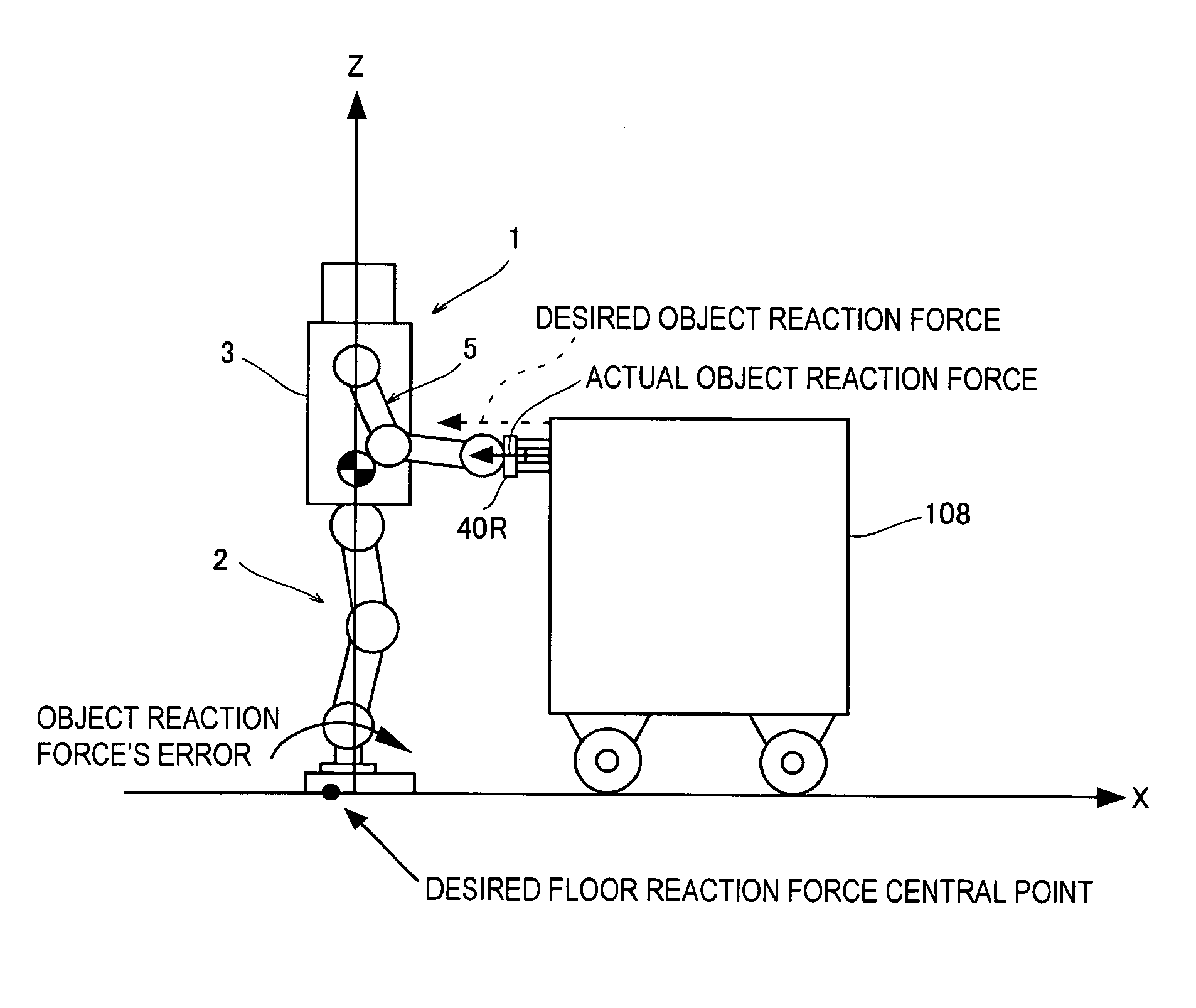
The present invention provides a posture control system for a mobile robot that can maintain dynamic balance and stability even when the robot encounters unexpected reaction forces or becomes unstable due to external factors. The system uses sensors to detect and estimate the actual reaction force and position / posture of the robot, and a controlling system to correct the desired motion to stabilize the robot's posture. This ensures that the robot can perform work with dynamic balance and without affecting the objects it encounters. The invention also provides a method for generating the desired motion based on the desired object reaction force and detecting and correcting posture inclination errors. Overall, the invention improves the stability and efficiency of mobile robots in various work environments.

Problems solved by technology

However, since the total floor reaction force's moment generated by the aforesaid technique has a limit, if trying to generate the total floor reaction force's moment beyond the limit, a part of a foot may be lifted up, resulting in the robot losing the dynamic balance or, at worst, tipping over.

Method used


Image

  • Attitude control device of mobile robot
  • Attitude control device of mobile robot
  • Attitude control device of mobile robot

Examples


second embodiment

[0278]FIG. 25 is a view showing a posture control system of a mobile robot according to the present invention.

[0279]Focusing on the points of difference from the first embodiment, in the second embodiment, among outputs from the object reaction force equilibrium control distributor 208, the sum of the object reaction force error moments to be equilibrated by object reaction force equilibrium control is made zero (indicated by the dashed line in the figure), whilst all outputs from the object reaction force equilibrium control distributor 208 are made only the sum of the object reaction force error moments to be equilibrated by the means other than the object reaction force equilibrium control.

[0280]Other configuration and effects are the same as those of the first embodiment. Since the posture control system of the mobile robot according to the second embodiment is thus configured, the same effects as in the system according to the first embodiment can be achieved.

third embodiment

[0281]FIG. 26 is a view showing a posture control system of a mobile robot according to the present invention.

[0282]Focusing on the points of difference from the first embodiment, in the third embodiment, instead of the biped mobile robot 1, posture control is implemented on a wheel mobile robot as shown in the figure.

[0283]Explaining this in the following, as illustrated, the wheel robot 300 has a cylindrical body 302 and four wheels (only two wheels are shown in the figure) 304 fixed thereto via active suspensions (not shown) that stroke up and down (in the Z-axis direction). A mount 306 is rotatably disposed at the top of the body 302 and a bendable arm (arm link) 310 is disposed thereon.

[0284]To be more specific, the arm 310 comprises a first link 310a fixed to the mount 306, a second link 310b connected to the first link 310a via a joint (not shown) and a hand 310c connected to the free end of the second link 310b via a joint (not shown). The respective joints accommodate actua...


PUM


Abstract

A posture control system for a mobile robot. When an unexpected external force acts, the system is configured to control and stabilize the posture of the robot driving an arm link such that, in response to a first external force that is a component in a predetermined direction of an unexpected external force, a second external force acts on the arm link in a direction orthogonal to the predetermined direction. With this, when the mobile robot receives a reaction force, even if the posture becomes unstable or the robot receives an unexpected reaction force, it becomes possible to preserve the dynamic balance and to maintain a stable posture.

Description

TECHNICAL FIELD TO WHICH THE INVENTION RELATES TO[0001]The present invention relates to a posture control system of a mobile robot, and specifically to a control system for ensuring a stable posture of a mobile robot, in particular a biped mobile robot or a wheel mobile robot having an arm(s), when the robot is controlled to perform a work that is likely to receive a reaction force from an object through the arm.BACKGROUND ART OF THE INVENTION[0002]The applicant discloses a posture control system of a legged mobile robot, for mobile robots, in Japanese Laid-Open Patent Application No. Hei 10 (1998)-230485. In this prior art, it is configured to displace the position of the center of gravity of the robot by correcting a posture gradually over a long period of time to displace a body of the robot so as to generate a moment of gravity for compensation, so as to maintain or preserve the dynamic balance, in particular the equilibrium that balances robot posture dynamically, when the robo...

Claims


Application Information

Patent Timeline
Patent Type & Authority Patents(United States)
IPC IPC(8): B25J5/00B25J13/00G06F19/00A63H11/18B62D57/02B62D57/032
CPCB62D57/032B62D57/02B25J9/06Y10S901/01
Inventor TAKENAKA, TORUHASEGAWA, TADAAKIMATSUMOTO, TAKASHI
Owner HONDA MOTOR CO LTD
Learn More