Active bias circuit for low-noise amplifiers

Inactive Publication Date: 2006-09-26
MARVELL INT LTD
View PDF12 Cites 12 Cited by
  • Summary
  • Abstract
  • Description
  • Claims
  • Application Information

AI Technical Summary

Benefits of technology

[0011]According to the second aspect, the feedback circuit includes a current source in communication with a second reference voltage and a comparator circuit. The comparator circuit includes a first input, a second input and an output. The output is in communication with the first impedance element. The feedback circuit includes a third impedance element in communication with the current source and the first input. The third impedance element is configured to generate a predetermined reference voltage corresponding to a predetermined reference current generated by the current source. The feedback circuit includes a fourth impedance element in communication with the second input and the second impedance element. The feedback circuit includes a third reference voltage in communication with the second and fourth impedance elements and the second input. The third reference voltage comprises a fifth impedance element and a fourth reference voltage. According to exemplary embodiments of the second aspect, the feedback circuit compares a voltage, corresponding to an output current associat

Problems solved by technology

Thus, under different conditions and varying transistor characteristics, the gain of the LNA can vary, which in most applications is unacceptable.
For a 50Ω incoming signal, such an impedance can be too lo

Method used


Image

  • Active bias circuit for low-noise amplifiers
  • Active bias circuit for low-noise amplifiers
  • Active bias circuit for low-noise amplifiers

Examples


Embodiment Construction

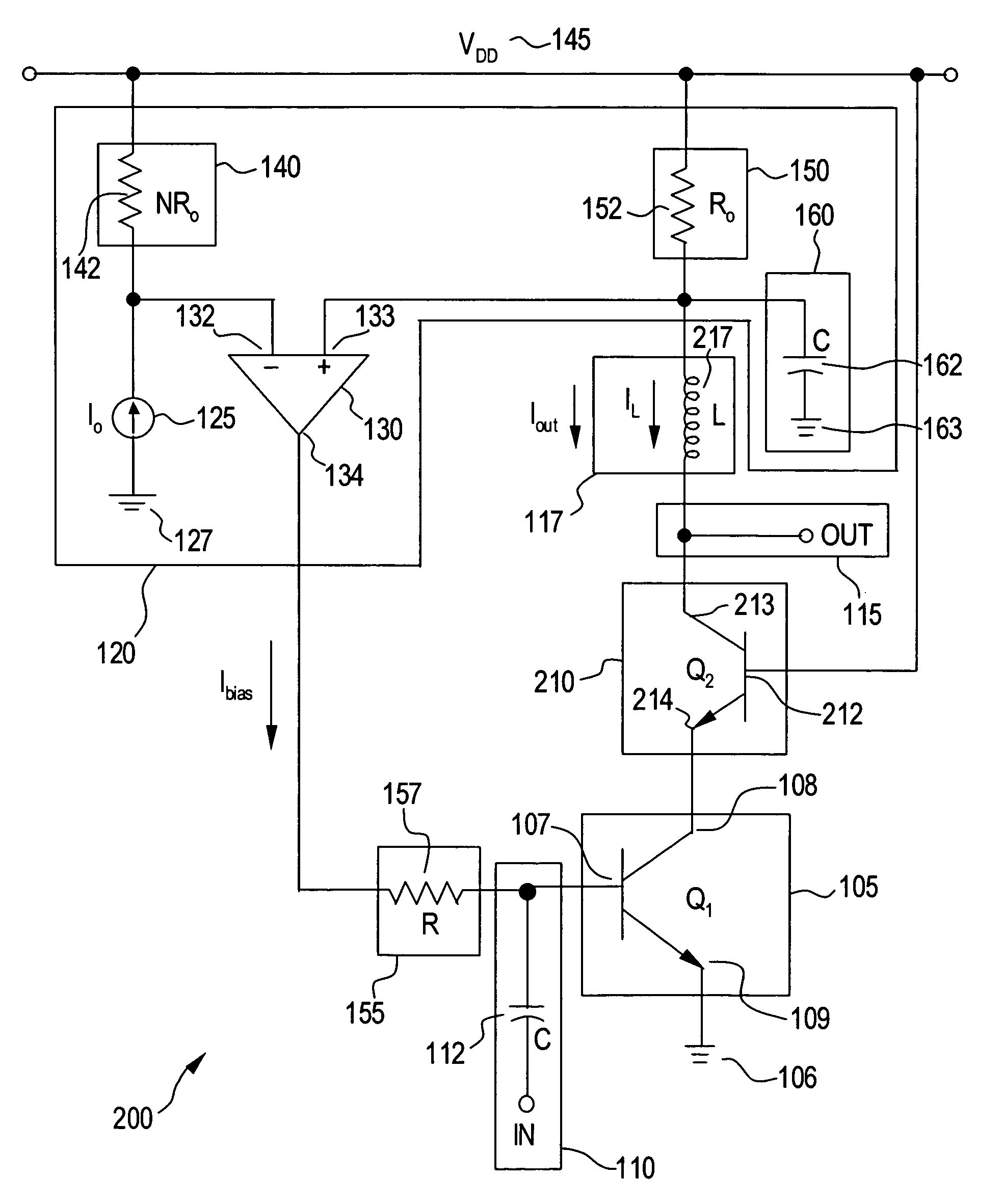
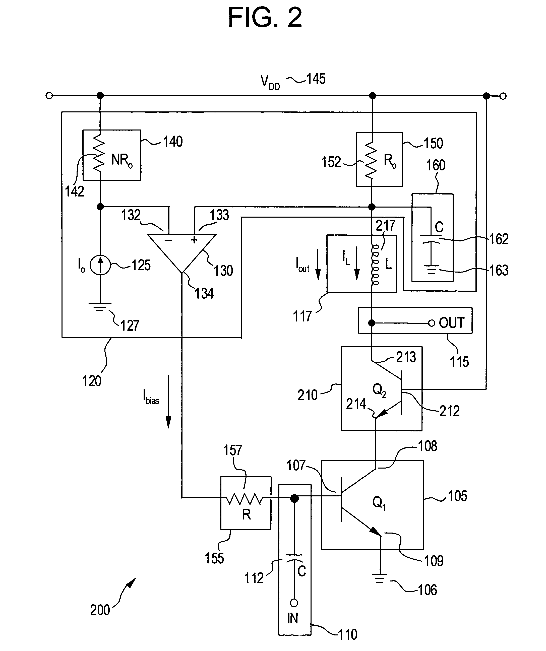
[0016]Exemplary embodiments of the present invention are directed to a system and method for actively controlling the bias of a low-noise amplifier (LNA). According exemplary embodiments, a feedback circuit in communication with the LNA is used. The feedback circuit senses the current in the LNA. The feedback circuit includes a comparator for comparing the sensed current with a reference current. The output of the comparator biases the input of the LNA by adjusting the current in the LNA until the LNA current reaches a predetermined level corresponding to the reference current. Exemplary embodiments of the present invention provide a means of biasing a LNA that is independent of process variations, transistor β variations, and other like variations in transistor characteristics.

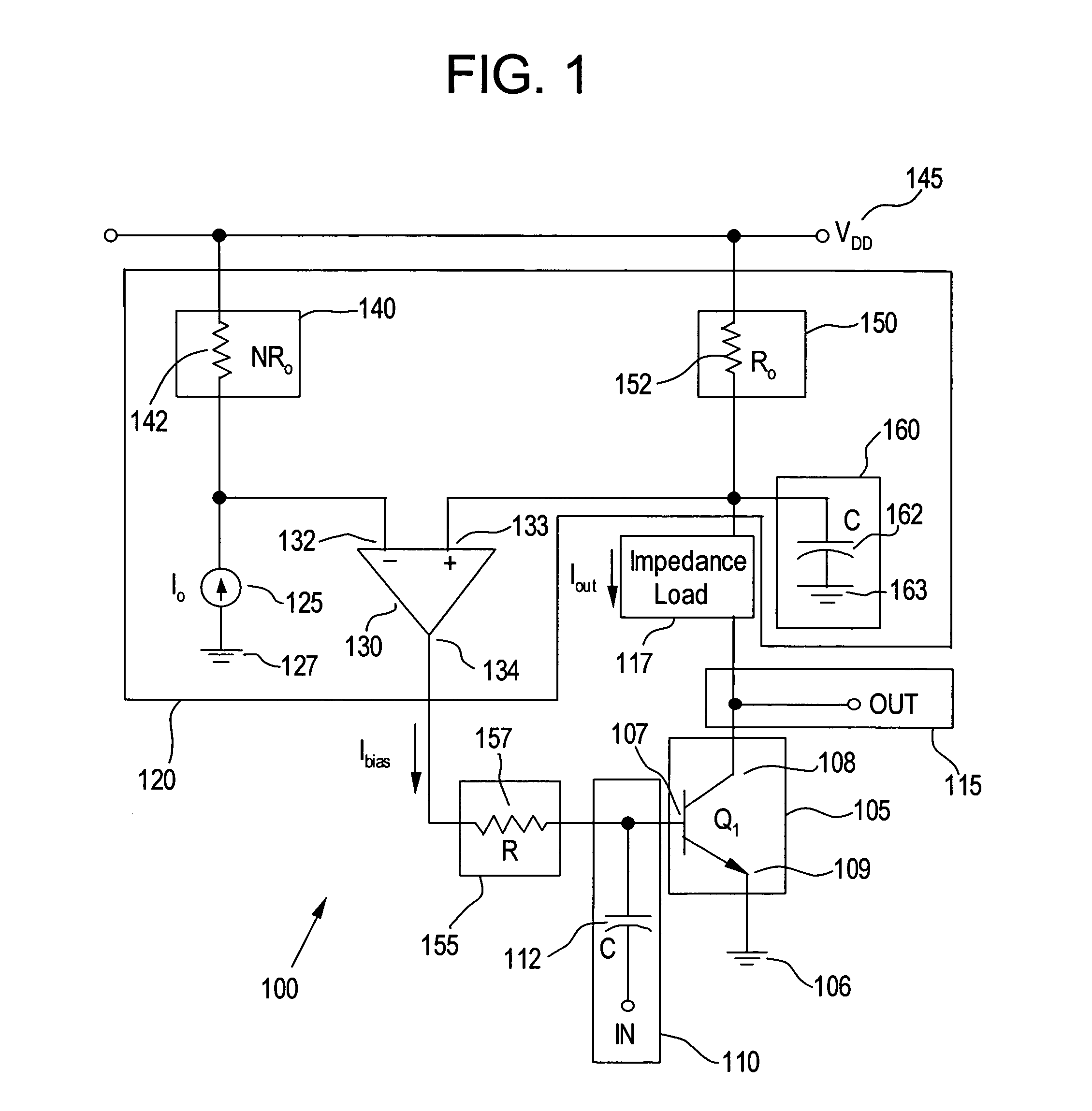
[0017]These and other aspects of the present invention will now be described in greater detail. FIG. 1 is a circuit diagram illustrating a system 100 for actively controlling a bias of a LNA, in accordance wi...


PUM


Abstract

A low-noise amplifier includes a first amplification device. The first amplification device includes a control terminal, a first terminal, and a second terminal. The low-noise amplifier also includes a feedback circuit in communication with the control terminal and the first terminal. The feedback circuit compares a voltage, corresponding to an output current associated with the first terminal, with a predetermined reference voltage to generate a bias signal applied to the control terminal for biasing the low-noise amplifier.

Description

BACKGROUND[0001]1. Field of the Invention[0002]The present invention relates to integrated circuits. More particularly, the present invention relates to an active bias circuit for low-noise amplifiers.[0003]2. Background Information[0004]Typically, in low-noise amplifiers (LNAs) and the like, it is desirable to reduce the contribution of noise from any component as much as possible. In bipolar circuitry, for example, a bias current is applied to the base of the transistor that comprises the LNA. However, due to process variations, temperature, and the like, the β of the transistor can vary by a factor of two, three, four or more. As a result of such varying transistor characteristics, the level of the bias current required to be applied to the transistor will change, resulting in a varying control of the gain of the LNA. Thus, under different conditions and varying transistor characteristics, the gain of the LNA can vary, which in most applications is unacceptable.[0005]To address t...

Claims


Application Information

Patent Timeline
IPC IPC(8): H03G3/10
CPCH03F1/26H03F1/30H03F3/343H03F2200/504H03F2200/294H03F2200/372
Inventor JIN, XIAODONGWEI, SHURAN
Owner MARVELL INT LTD
Why Eureka
Try Eureka