Piezoelectric resonator, method of manufacturing piezoelectric resonator, and filter, duplexer, and communication device using piezoelectric resonator

a piezoelectric resonator and piezoelectric technology, applied in the direction of piezoelectric/electrostrictive/magnetostrictive devices, transducers, electrical transducers, etc., can solve the problems of spurious vibration, communication quality degradation, and the entire piezoelectric resonator does not make free vertical vibration, etc., to achieve the effect of simplifying manufacturing processes

Inactive Publication Date: 2006-09-26
PANASONIC CORP
View PDF8 Cites 11 Cited by
  • Summary
  • Abstract
  • Description
  • Claims
  • Application Information

AI Technical Summary

Benefits of technology

[0033]According to the present invention, a spurious resonant frequency can be removed from a resonant frequency and an anti-resonant frequency. Also, such a spurious resonant frequency can be separated from the resonant frequency. Thus, spurious resonance can be suppressed in a predetermined band. Therefore, when the piezoeletric resonator is used for a filter, spurious resonance can be moved outside of the pass-band, thereby achieving a flat band-pass characteristic.
[0037]Furthermore, according to the present invention, only with a simple process of determining the depth of the cavity, a piezoeletric resonator achieving a spurious-resonance suppressing effect can be manufactured. That is, no additional process for suppressing spurious resonance is required, thereby simplifying the manufacturing processes.

Problems solved by technology

In practice, since the piezoelectric resonator is partially fixed to the substrate, the entire piezoelectric resonator does not make free vertical vibrations.
With the main resonant vibration leaked to the substrate, spurious vibration occurs.
As a result, quality degradation in communications occurs.

Method used


Image

  • Piezoelectric resonator, method of manufacturing piezoelectric resonator, and filter, duplexer, and communication device using piezoelectric resonator
  • Piezoelectric resonator, method of manufacturing piezoelectric resonator, and filter, duplexer, and communication device using piezoelectric resonator
  • Piezoelectric resonator, method of manufacturing piezoelectric resonator, and filter, duplexer, and communication device using piezoelectric resonator

Examples


first embodiment

[0066](First Embodiment)

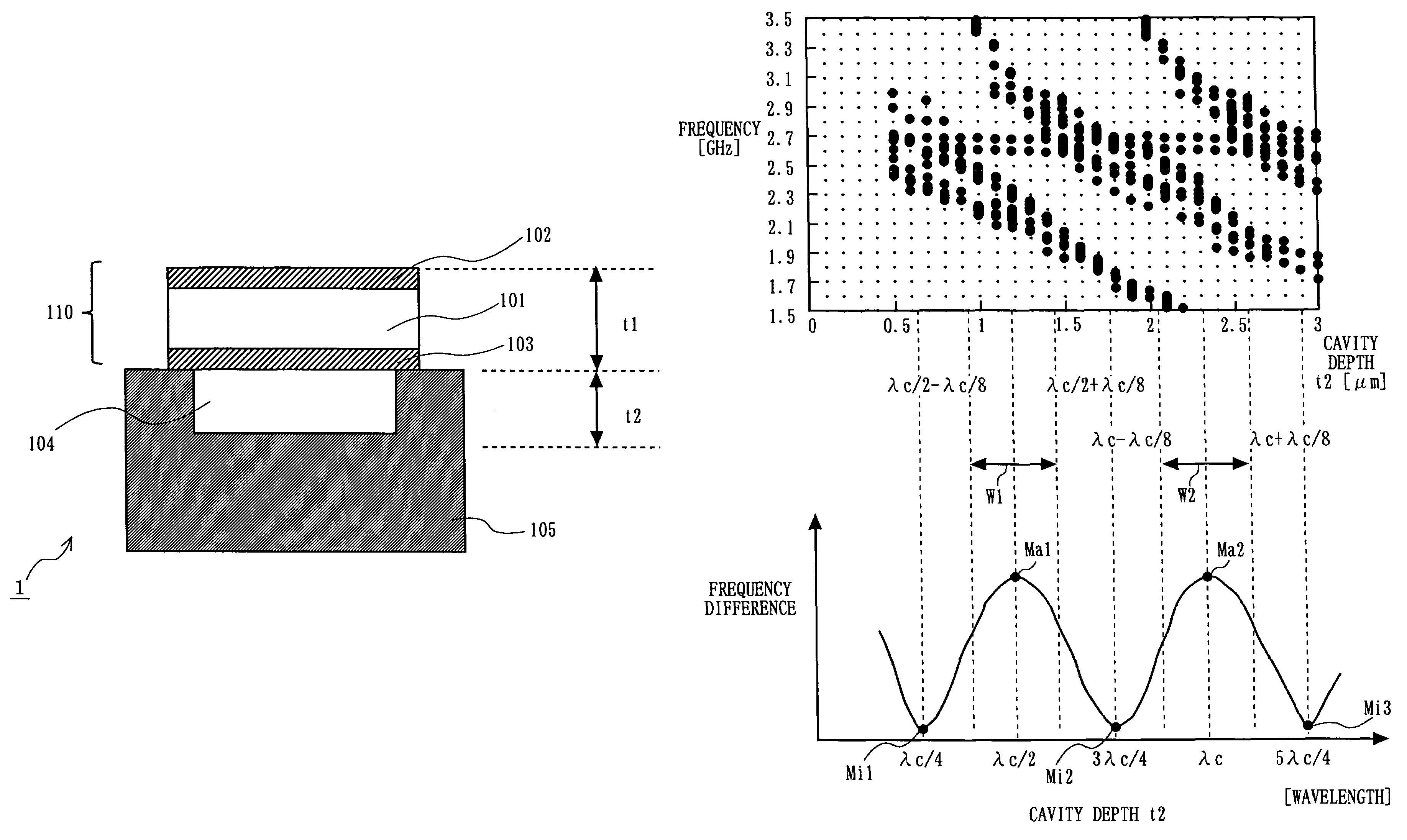
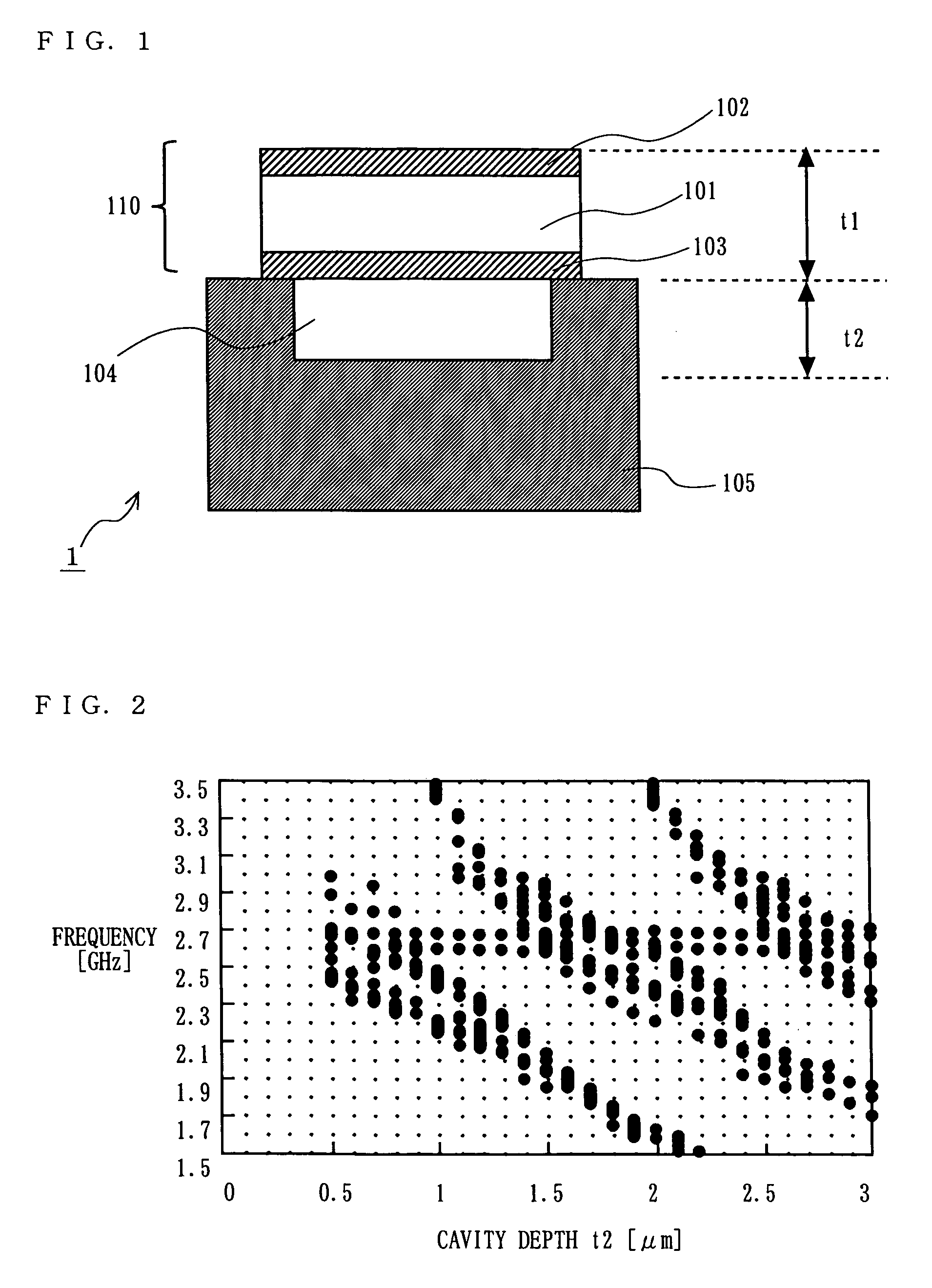
[0067]FIG. 1 is a section view of a piezoelectric resonator 1 according to a first embodiment of the present invention. In FIG. 1, the piezoelectric resonator 1 includes a piezoelectric body 101, an upper electrode 102, a lower electrode 103, a cavity 104, and a substrate 105.

[0068]The lower electrode 103 is formed on the substrate 105 with, for example, molybdenum (Mo), tungsten (W), aluminum (Al), titanium (Ti), copper (Cu), platinum (Pt), or gold (Au).

[0069]The piezoelectric body 101 is formed on the lower electrode with an appropriate piezoelectric material, such as zinc oxide (ZnO), lead zirconate titanate (PZT), or aluminum nitride (AlN).

[0070]The upper electrode 102 is formed on the piezoelectric body 101 with, for example, molybdenum (Mo), tungsten (W), aluminum (Al), titanium (Ti), copper (Cu), platinum (Pt), or gold (Au).

[0071]The cavity 104 is formed on an upper portion of the substrate 105 below the lower electrode 103. The cavity 104 has a rectan...

second embodiment

[0094](Second Embodiment)

[0095]The structure of a piezoeletric resonator according to a second embodiment is similar to that of the first embodiment, and therefore FIG. 1 is also referred to. In the second embodiment, a resonant frequency fr is based on vibration (½ vibration) with the thickness of the vibrating portion 110 being taken as a half wavelength (λp / 2). Also, an average of ultrasonic velocity in the material of the cavity 104 (in the substrate 105) is taken as Vc. Furthermore, a value determined based on the resonant frequency fr and the average of ultrasonic velocity Vc is represented as λc (=Vc / fr). In the second embodiment, the depth t2 of the cavity 104 is set so as not to satisfy (2n−1)×λc / 4, where n is an integer. Here, when a member (for example, the substrate) forming the cavity is made of a plurality of materials, λc is derived based on an average of ultrasonic velocity Vc in each of these materials (this applies to all of the following embodiments).

[0096]FIG. 4A...

third embodiment

[0109](Third Embodiment)

[0110]The structure of a piezoeletric resonator according to the third embodiment is similar to that of the first embodiment, and therefore FIG. 1 is also referred to. In the third embodiment, the depth t2 of the cavity 104 is set as n×λ / 2 (n is an integer).

[0111]As shown in FIG. 4B, if the depth t2 of the cavity 104 is set as n×λ / 2, the difference between the main resonant frequency and a spurious resonant frequency closest to the main resonant frequency is the maximum. As a result, no spurious resonant frequency is present near the main resonant frequency.

[0112]FIG. 5A is a graph showing an admittance characteristic when the depth of the cavity 104 is set as λ / 2. That is, FIG. 5A is a gram showing an admittance characteristic at the point Ma1 in FIG. 4B.

[0113]FIG. 5B is a graph showing an admittance characteristic when the depth of the cavity 104 is set close to 3λc / 4. That is, FIG. 5B is a gram showing an admittance characteristic at the point Mi2 in FIG. ...


PUM

PropertyMeasurementUnit
resonant frequenciesaaaaaaaaaa
depthsaaaaaaaaaa

Abstract

A piezoeletric resonator includes: a substrate; a lower electrode formed on or above the substrate; a piezoeletric body formed on or above the lower electrode; an upper electrode formed on or above the piezoeletric body; and a cavity under a vibrating portion formed by the lower electrode, the piezoeletric body, and the upper electrode. Where a resonant frequency of vibration with a thickness of the vibrating portion being a half of a wavelength is taken as fr, an average of ultrasonic velocity in a material forming the cavity is taken as Vc, and a value determined based on the resonant frequency fr and the average of ultrasonic velocity Vc is taken as λc (=Vc / fr), a depth of the cavity is set so as to be equal to or larger than n×λc / 2−λc / 8 and equal to or smaller than n×λc / 2+λc / 8.

Description

BACKGROUND OF THE INVENTION[0001]1. Field of the Invention[0002]The present invention relates to a piezoelectric resonator, a method of manufacturing such a piezoelectric resonator, and a filter, a duplexer, and a communication device using such a piezoelectric resonator. More specifically, the present invention relates to a piezoelectric resonator improved so as to be able to remove spurious components, a method of manufacturing such a piezoelectric resonator, and a filter, a duplexer, and a communication device using such a piezoelectric resonator.[0003]2. Description of the Background Art[0004]Components incorporated in electronic devices such as cellular phones are required to be small in size and weight. For example, a filter for use in a cellular phone is required to be small in size and be precisely adjusted in frequency characteristic.[0005]One of known filters satisfying such requirements is a filter using a piezoelectric resonator (for example, refer to Japanese Patent Lai...

Claims


Application Information

Patent Timeline
Patent Type & Authority Patents(United States)
IPC IPC(8): H03H9/70H03H3/02H03H9/15H03H9/54H03H3/04H03H9/02H03H9/17H03H9/56
CPCH03H3/04H03H9/173H03H9/0211Y10T29/42H03H9/15
Inventor NAKATSUKA, HIROSHIONISHI, KEIJINAKAMURA, HIROYUKIYAMAKAWA, TAKEHIKOYAMAGUCHI, HIROSHI
Owner PANASONIC CORP
Why Eureka
Try Eureka