Condition monitoring in technical processes

a technology for condition monitoring and technical processes, applied in the field of system for monitoring technical processes, machines, installations and apparatuses, can solve the problems of large cost expenditure, inability to monitor the condition of the equipment, so as to avoid the loss of valuable materials, prolong the service life, and improve the reliability

Active Publication Date: 2006-09-26
RENNER PETER
View PDF5 Cites 4 Cited by
  • Summary
  • Abstract
  • Description
  • Claims
  • Application Information

AI Technical Summary

Benefits of technology

[0004]It is an object of the invention to make a contribution in order that machines and installations are better utilized, their service life is extended, reliability is improved, the loss of valuable materials is avoided, test results are optimized, and energy consumption is diminished. It is a further object of the invention to detect and report promptly the threat of total failures (crashes). Operational malfunctions and instrumentation malfunctions that play out on a scale of seconds or minutes should likewise be detected.
[0013]A further embodiment of the invention makes it possible to identify the quasi-static phase of operation. The identification channels serve for identifying the quasi-static phase. A test is continually performed to ascertain whether the quasi-static phase is in effect. This is done by calculating identification conditions that relate to the identification channels.
[0022]In order to specify what deviations have arisen, supply indications of operational malfunctions, warn of imminent total failures, and give instructions to perform corrective work associated with the condition of the machines or installations, it is proposed in a further inventive step that the measured values of the condition channels of the reference groups be compressed into statistical condition values, preferably into means. The compression is based on a selection of the ordinary time ranges or a multiple thereof, such as second values, minute values, hour values, day values, week values, month values or year values. In this way it becomes possible to detect slow, moderately fast and fast variations in the measured values.

Problems solved by technology

Changes in machines, apparatuses and installations are caused by wear, corrosion, deposits, plugging, contamination, and nonspecifically occurring operational malfunctions.
They have the disadvantage that a very great cost expenditure is occasioned because the application in question must be trained.
The results obtained are rather meager.
Other methods also address only partial aspects and have not met with total success.
The difficulty in assessing a machine condition results from the following circumstances.
Small changes in the temperature values of bearing positions, for example, are significant for the degree of wearing-out of the bearings.
It is therefore not possible, according to the existing art, to track small changes, because service-associated fluctuations in the measured values are larger than the small changes attributable to bearing wear.

Method used


Image

  • Condition monitoring in technical processes
  • Condition monitoring in technical processes
  • Condition monitoring in technical processes

Examples


Embodiment Construction

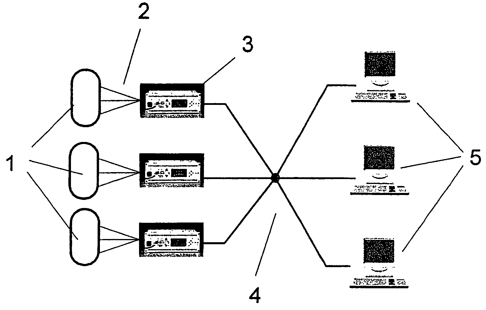
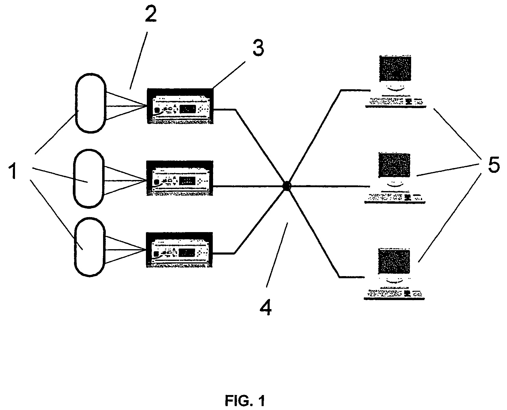
[0036]The reference characters in FIG. 1 have the following meanings:[0037]1 processes that are being monitored;[0038]2 lines serving as connections between the sensors of the processes and measurement units;[0039]3 measurement units as interfaces between the processes and the PCs;[0040]4 a data network serving as data connection between the measurement units and the PCs; and[0041]5 PCs on which the monitoring software is installed.

[0042]The function according to FIG. 1 is next described. Measurement units 3 serve as interface between processes 1 whose condition is to be monitored. In processes 1 there are sensors, which are connected to measurement units 3 via connecting lines 2. Measurement units 3 are in turn connected to PCs 5 via data network 4. In this way, analog and digital signals of the sensors can be conveyed to the PCs. The governing software, which carries out monitoring tasks in combination with the functions of the measurement units, is installed on PCs 5.

[0043]The re...


PUM


Abstract

The invention makes a contribution in order that machines and installations are better utilized, their service life is extended, reliability is improved, the loss of valuable materials is avoided, test results are optimized, and energy consumption is diminished. It is an expert system that acquires and assesses the condition of installations, machines and apparatuses. The mechanism proceeds from a normal condition and permanently observes short-term, medium-term and long-term changes. If variations in the normal condition are detected promptly, major instances of damage can be avoided by promptly performing corrective actions before major instances of damage associated with prolonged downtimes occur.

Description

BACKGROUND OF THE INVENTION[0001]The invention relates to a system for monitoring technical processes, machines, installations and apparatuses. If changes in the normal condition are detected promptly, major instances of damage can be avoided by promptly performing corrective actions before major instances of damage associated with prolonged downtimes occur. Changes in machines, apparatuses and installations are caused by wear, corrosion, deposits, plugging, contamination, and nonspecifically occurring operational malfunctions.[0002]First approaches to machine condition monitoring with an eye to crash prevention and condition-oriented maintenance are based on complicated mathematical calculations preferably based on neuronal networks. They have the disadvantage that a very great cost expenditure is occasioned because the application in question must be trained. The results obtained are rather meager. Other methods also address only partial aspects and have not met with total success...

Claims


Application Information

Patent Timeline
Patent Type & Authority Patents(United States)
IPC IPC(8): G06F17/40G05B23/02
CPCG05B23/024G05B2219/42271G05B2219/33027
Inventor RENNER, PETER
Owner RENNER PETER
Why Eureka
Try Eureka