
Flow pulsing valve and fuel supply system for a turbine engine incorporating same

a technology of turbine engines and fuel supply systems, which is applied in the direction of diaphragm valves, reciprocating combination engines, engine diaphragms, etc., can solve the problems of frequent combustion instabilities, damage to the combustor, and technology that is not suitable for commercial production applications, so as to simplify engine control

Active Publication Date: 2006-10-03
WOODWARD GOVERNOR CO
View PDF2 Cites 13 Cited by
  • Summary
  • Abstract
  • Description
  • Claims
  • Application Information

AI Technical Summary

Benefits of technology

The solution effectively dampens combustion oscillations over a wide range of operating conditions with lower costs and improved reliability, making it suitable for commercial applications by maintaining engine control accuracy and extending the lifespan of the system.

Problems solved by technology

Combustion instabilities frequently are encountered during the development and use of modern industrial gas turbine engines, especially engines that have low NOx technology.
The pressure oscillation caused by the instability can damage the combustor.
However, the technology has not been suitable for commercial production applications.
This proposed technology to date is expensive, has performance limitations due to very low stroke, and has limited life.
None of these references have provided a suitable solution for commercial production due to one or more of the following issues: cost, performance limitations, reliability, lifespan concerns, and / or other such concerns.

Method used


Image

  • Flow pulsing valve and fuel supply system for a turbine engine incorporating same
  • Flow pulsing valve and fuel supply system for a turbine engine incorporating same
  • Flow pulsing valve and fuel supply system for a turbine engine incorporating same

Examples


Embodiment Construction

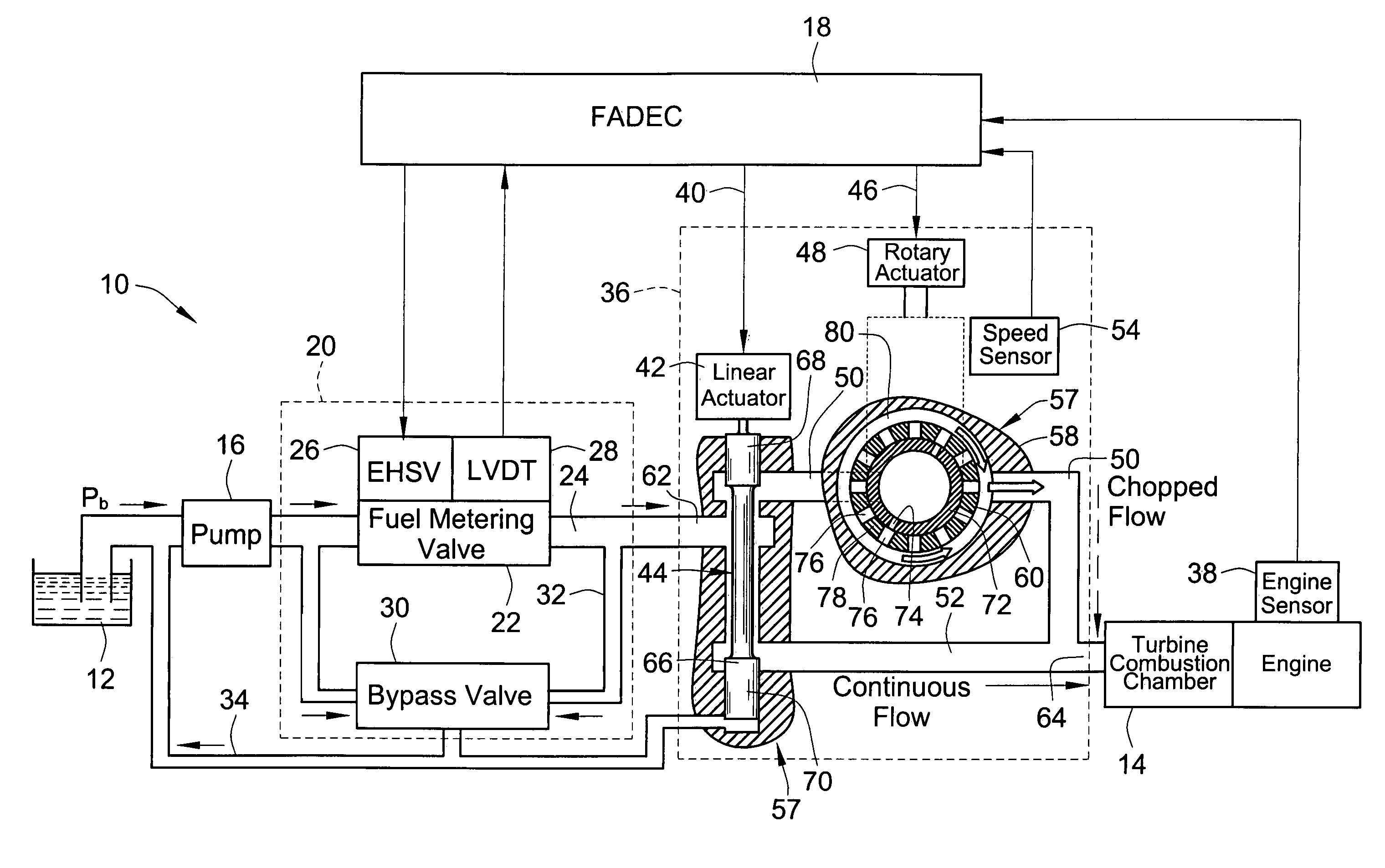
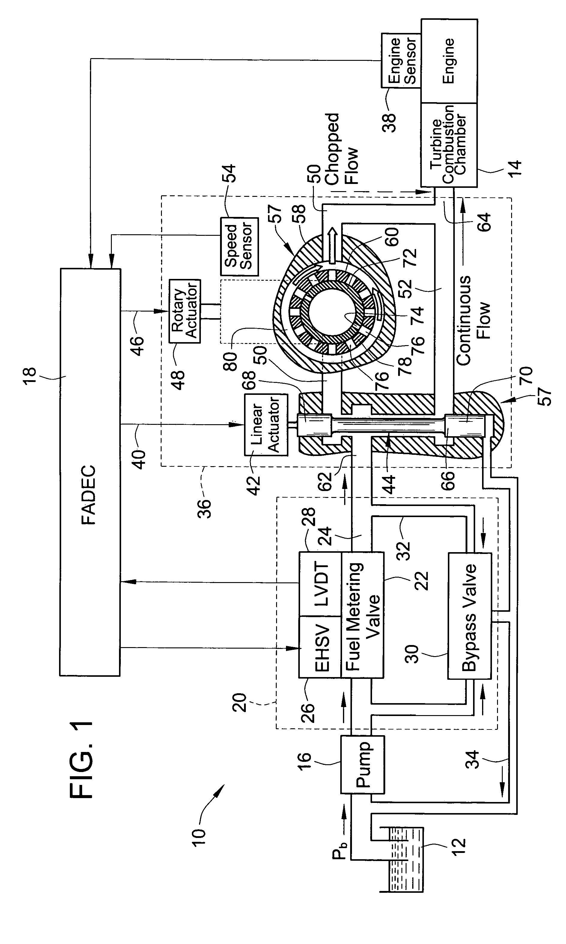
[0021]Referring to FIG. 1, a schematic representation of a liquid fuel supply system 10 for a turbine engine is illustrated in accordance with an embodiment of the present invention. A gas system will be slightly different. The pressure output of the pump is regulated by virtue of the compressible nature of gas rather than a bypass valve. The fuel supply system generally supplies liquid or gaseous fuel from a fuel source such as a fuel tank 12 to the turbine combustion chamber 14 where the fuel is ignited. The fuel supply system 10 may include a pump 16 arranged in series with the fuel tank 12 to pressurize and pump fuel toward the turbine combustion chamber 14.

[0022]In modern systems, an electronic controller is provided for electronically controlling the flow of fuel to the combustion chamber. Accordingly, FIG. 1 schematically illustrates an electronic controller in the form of a full authority digital electrical control or what is referred to as the FADEC 18 that electronically c...


PUM


Abstract

A pulsing valve assembly pulses metered fuel flow to a turbine engine. The pulsing valve assembly comprises a valve housing having an inlet and an outlet. A divider valve divides metered fuel flow into a first flow portion and a second flow portion. A first actuator sets a magnitude of a flow divide between the first and second flow portions. The valve assembly also includes a pulsing valve for pulsing the first flow portion and a second actuator for setting a frequency of pulsing valve. The pulsed and unpulsed flow portions are then joined and delivered to the turbine engine combustion chamber.

Description

FIELD OF THE INVENTION[0001]The present invention generally relates to flow control valves, and more particularly relates to flow pulsing valves and / or applications of such valves in turbine engine fuel supply systems.BACKGROUND OF THE INVENTION[0002]Combustion instabilities frequently are encountered during the development and use of modern industrial gas turbine engines, especially engines that have low NOx technology. These low pollution engines operate at fuel mixtures that can result in combustor instabilities at frequencies up to 700 Hz or even higher. The pressure oscillation caused by the instability can damage the combustor. Often, during engine development, the combustor geometry is modified to correct these instabilities. These modifications are called passive techniques and are generally effective for a limited range of operating conditions. Recently, active control methods have been successfully tested in a laboratory environment. Active control means that some engine p...

Claims


Application Information

Patent Timeline
Patent Type & Authority Patents(United States)
IPC IPC(8): F02C7/22F02C9/26
CPCF02C9/263F02C9/266Y10T137/86718
Inventor HOMMEMA, EDWARD L.
Owner WOODWARD GOVERNOR CO
Learn More