Cavity on-board injection for leakage flows

a gas turbine engine and valve body technology, applied in the direction of liquid fuel engines, machines/engines, mechanical equipment, etc., can solve the problems of affecting not without a negative effect, extreme temperatures to which the engine components, particularly the turbine blades, are exposed, and the flow of air in the direction of the transverse direction of the flow is necessary to detract from the efficiency of the engin

Active Publication Date: 2006-10-03
RTX CORP
View PDF18 Cites 48 Cited by
  • Summary
  • Abstract
  • Description
  • Claims
  • Application Information

AI Technical Summary

Problems solved by technology

While effective, difficulties encountered in the design and operation of gas turbine engines result from the extreme temperatures to which the engine components, particularly the turbine blades, are exposed.
While such devices are effective in directing cooling or parasitic leakage air into the turbine section, it is not without detrimental effect.
As the turbines are driven by this axial gas flow path of the combustion gases, any influx of air in a direction transverse to that flow necessarily detracts from the efficiency of the engine.

Method used


Image

  • Cavity on-board injection for leakage flows
  • Cavity on-board injection for leakage flows
  • Cavity on-board injection for leakage flows

Examples


Embodiment Construction

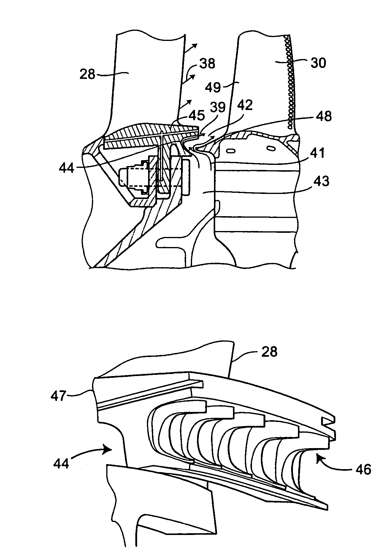
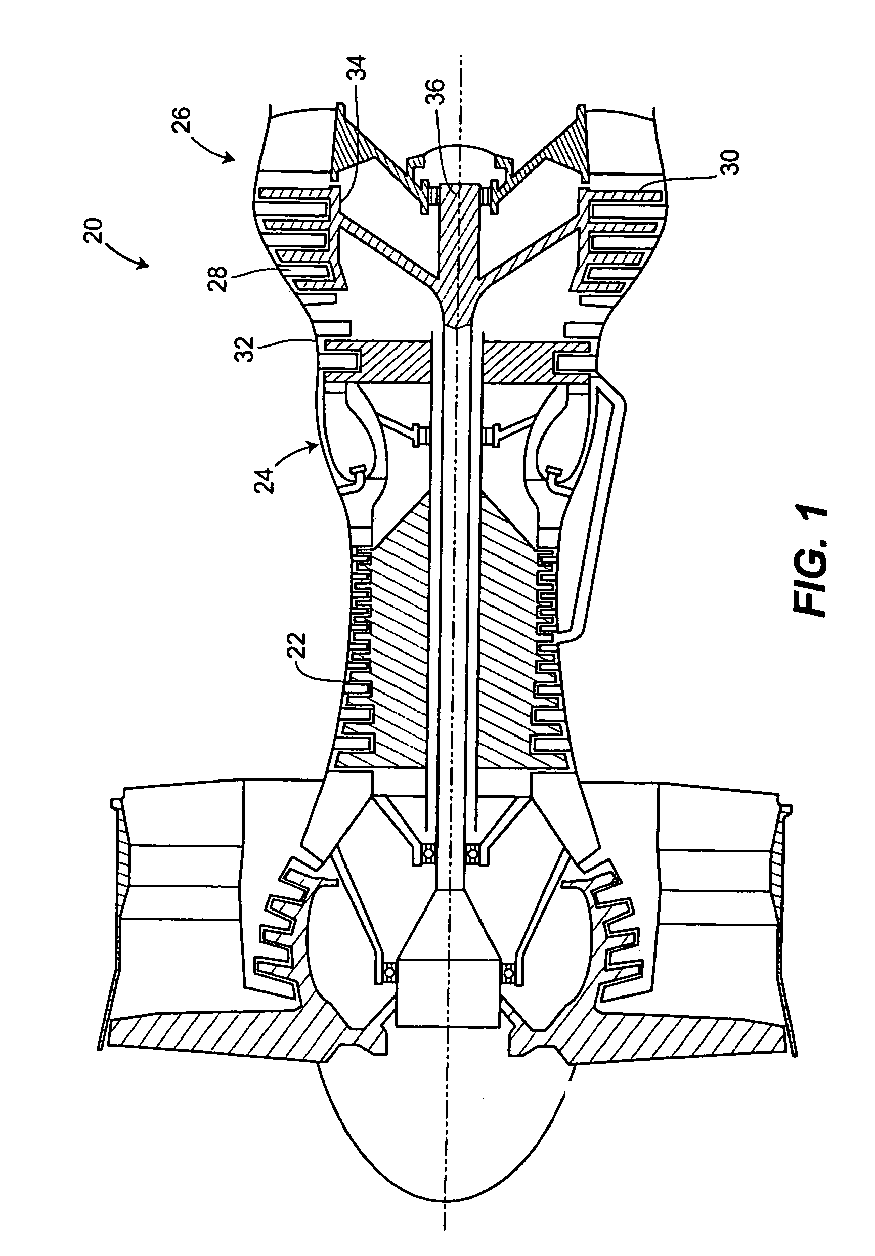
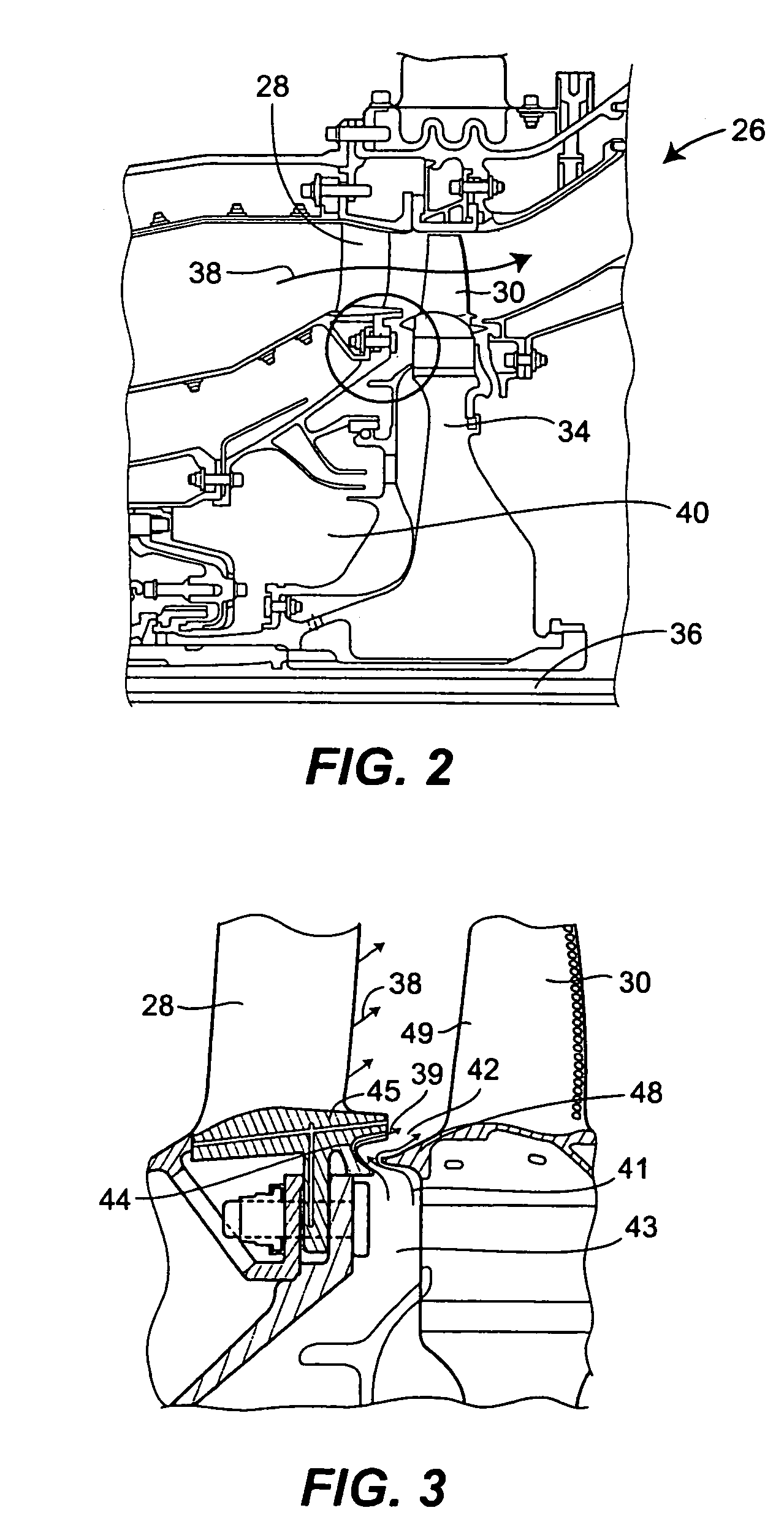
[0027]Referring now to the drawings, and with specific reference to FIG. 1, a gas turbine engine constructed in accordance with the teachings of the disclosure is generally referred to by reference numeral 20. As one with ordinary skill in the art will readily recognize, the gas turbine engine 20 includes a compressor section 22, a combustion section 24, and a turbine section 26. Generally, ambient air is compressed within compressor section 22, and directed to combustion section 24 where it is combined with fuel and ignited. The hot combustion gases resulting from ignition are then directed to the turbine section 26 and cause the turbine section to rotate and exhaust air at extremely high velocities.

[0028]The turbine section 26 includes a plurality of stator vanes 28 intermeshed with a plurality of rotor blades 30. The stator vanes 28 are fixedly mounted to casing 32 and extend radially inwardly, whereas the rotor blades 30 are mounted to a rotatable rotor 34 and extend radially ou...


PUM


Abstract

A gas turbine engine having a turbine section cooling system is disclosed which is able to cool the turbine section of the gas turbine engine to an optimal operating temperature range, while at the same time not substantially degrading engine performance. The disclosure provides a number of different structures for doing so including the provision of turning foils, turning holes, and turning grooves within a secondary air flow cavity which turns or directs cooling and parasitic leakage air into the turbine section in a direction in substantial alignment with a gas flow path through the turbine section.

Description

FIELD OF THE INVENTION[0001]The present disclosure generally relates to gas turbine engines and, more particularly, relates to the turbine section of gas turbine engines.BACKGROUND OF THE DISCLOSURE[0002]Gas turbine engines are widely applied machines for generating power or thrust. Most typically, they are employed on modern aircraft to provide the propulsion necessary for flight. They may also be used on board such aircraft for power generations or in an APU (Auxiliary Power Unit) capacity to provide for onboard heating, cooling, and ventilation, as well as the operational power and lighting systems onboard the aircraft within the cockpit, passenger cabin, and the like. They may also be used in land-based applications for generation of electrical power or mechanical horsepower in myriad vehicles and pieces of machinery.[0003]In a typical gas turbine engine, three main sections are provided, namely, a compressor section, a combustion section, and a turbine section. Within the compr...

Claims


Application Information

Patent Timeline
Patent Type & Authority Patents(United States)
IPC IPC(8): F02C7/12F01D11/00F01D5/08F01D5/18F01D25/12F02C7/18
CPCF01D5/081F01D25/12F02C7/18Y02T50/676F05D2260/60F05D2260/6022F05D2240/81Y02T50/60
Inventor ALVANOS, IOANNISAGRAWAL, RAJENDRAPINERO, HECTOR M.HU, JIN
Owner RTX CORP
Why Eureka
Try Eureka