All electric LNG system and process

a technology of lng process and all electric power, which is applied in the direction of gaseous fuels, machines/engines, light and heating apparatus, etc., can solve the problems of difficult adjustment of fossil fuel fired turbines, unsatisfactory variations, and less efficient operation of lng process, so as to improve efficiency and reduce carbon dioxide emissions

Active Publication Date: 2006-10-03
BP CORP NORTH AMERICA INC
View PDF14 Cites 55 Cited by
  • Summary
  • Abstract
  • Description
  • Claims
  • Application Information

AI Technical Summary

Benefits of technology

[0006]According to the present invention, improved efficiency is accomplished by a reduced carbon dioxide emissions method for providing power for refrigerant compression to a light hydrocarbon gas liquefaction process, the method comprising: a) providing electrical power for the light hydrocarbon gas liquefaction process from at least one source; and, b) compressing a low-pressure refrigerant to an increased pressure in at least one refrigerant compressor driven by an electric motor powered with the electrical power from a).

Problems solved by technology

This introduced undesirable variations into the LNG process since a constant flow of compressed refrigerant could not be assured.
The fossil fuel fired turbines are difficultly adjusted to overcome these changes and as a result the operation of the LNG process has been less efficient and has produced less LNG over defined periods of time.

Method used


Image

  • All electric LNG system and process
  • All electric LNG system and process

Examples


Embodiment Construction

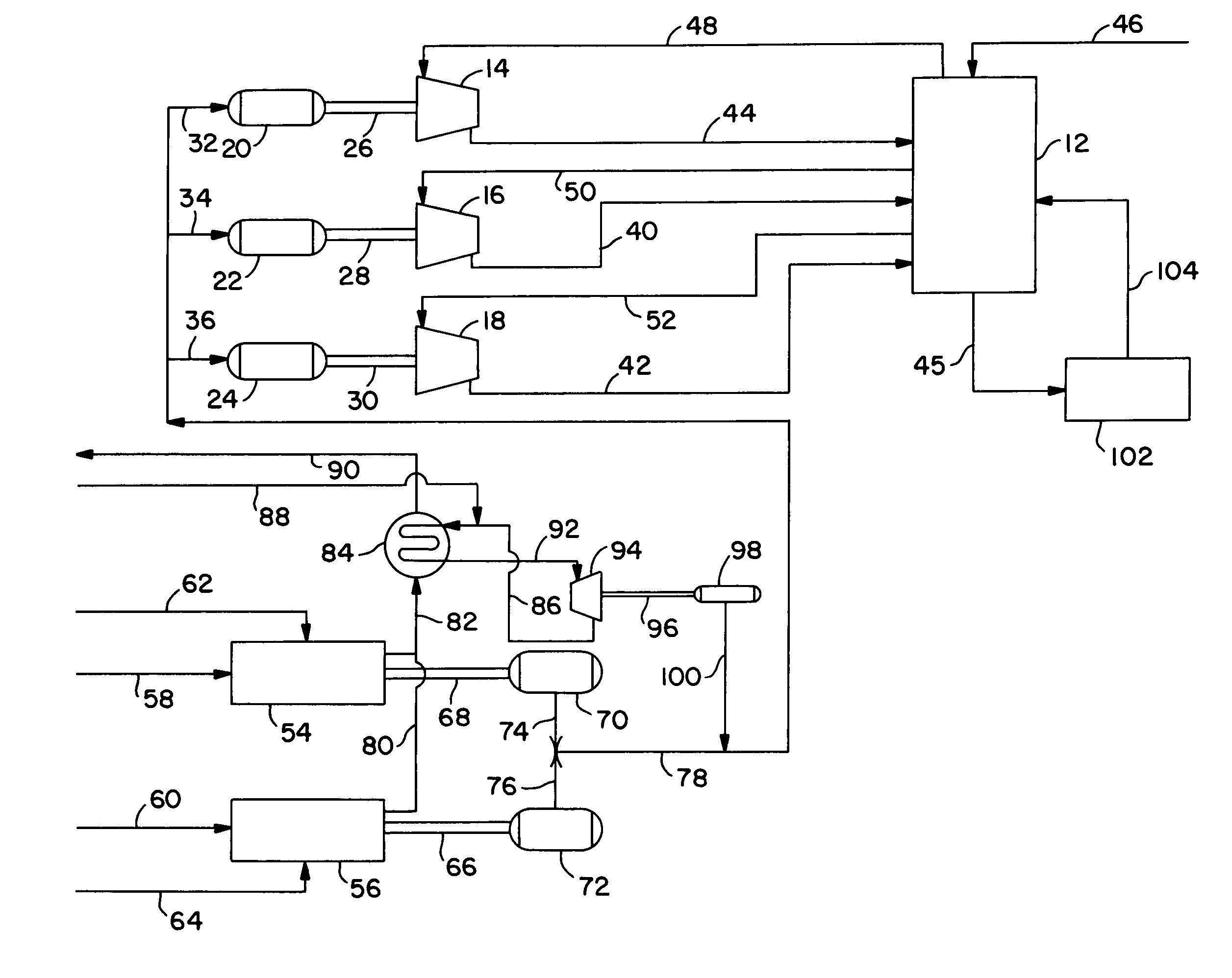
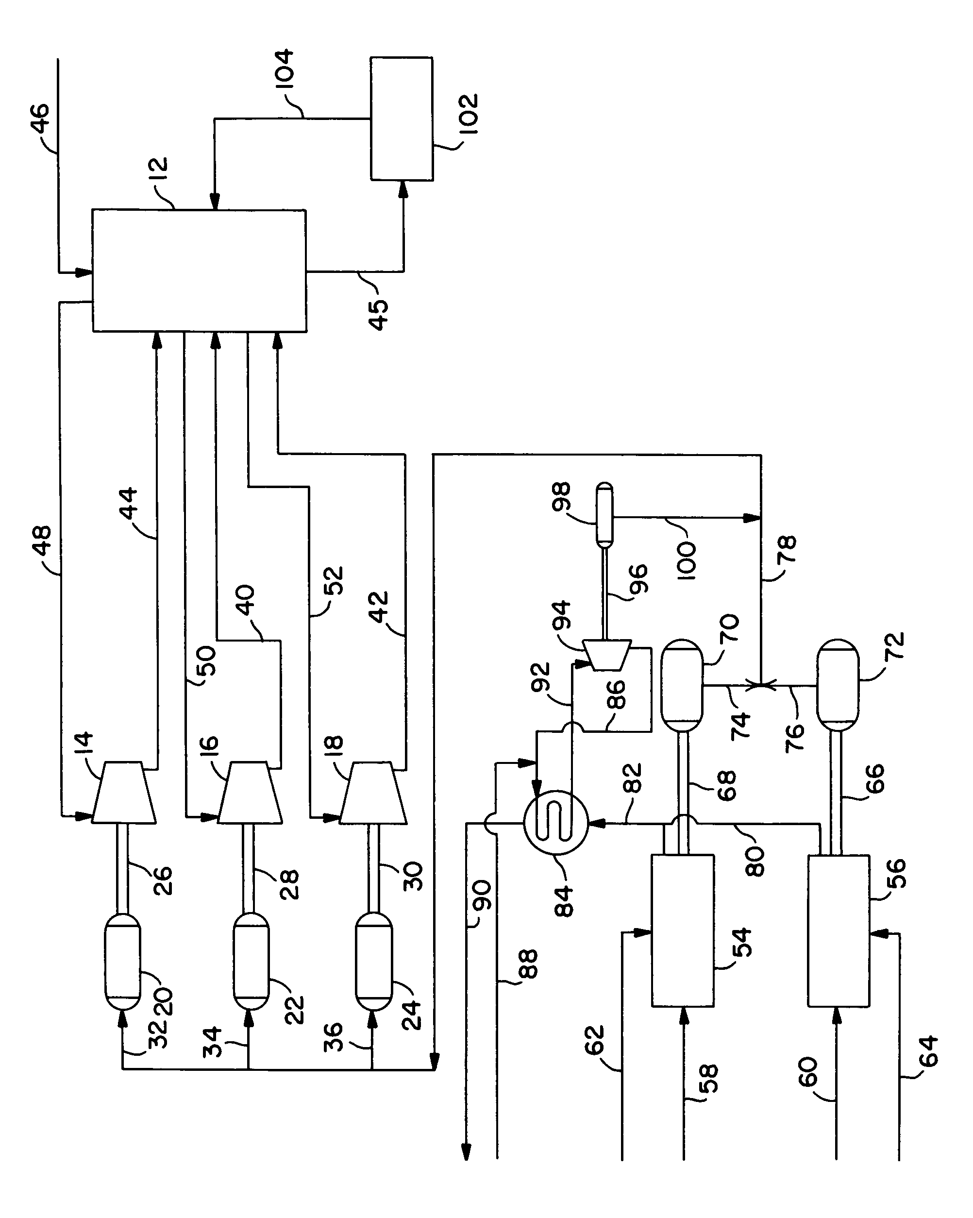
[0011]In the description of the FIGURE, numerous pumps, compressors, valves and the like necessary to accomplish the flows as shown have not been included for simplicity.

[0012]In the FIGURE, a light hydrocarbon gas liquefaction system and process is shown. As previously mentioned, such systems and processes are most commonly used for natural gas liquefaction and are referred to as LNG processes. As shown in the FIGURE, liquefaction plant facilities 12 are supplied with compressed refrigerant by three refrigerant compressors 14, 16 and 18 (typically at pressures from about 1 to about 75 bara). Electric motors 20, 22 and 24 power these refrigerant compressors via shafts 26, 28 and 30, although other linkages could be used as desired. While three electric motors and refrigerant compressors are shown as an illustration, fewer or more could be used. It will be further understood that the liquefaction plant facilities may include a plurality of refrigeration units selected from a wide var...


PUM

PropertyMeasurementUnit
pressureaaaaaaaaaa
pressureaaaaaaaaaa
temperatureaaaaaaaaaa

Abstract

A reduced carbon dioxide emissions system and method for providing power for refrigerant compression and shared electrical power for a light hydrocarbon gas liquefaction process.

Description

RELATED APPLICATIONS[0001]This application is entitled to and hereby claims the benefit of the filing date of U.S. Provisional Application No. 60 / 414,806 filed Sep. 30, 2002.FIELD OF THE INVENTION[0002]This invention relates to the liquefaction of light hydrocarbon gases, such as natural gas, by cooling the light hydrocarbon gases to a temperature at which they become liquid. The liquefaction process is carried out using substantially all electrically powered equipment.[0003]The invention further comprises a reduced carbon dioxide emission system for producing power for refrigerant compression and shared electrical power for a light hydrocarbon gas liquefaction process.[0004]Typically the light hydrocarbon gas is natural gas, which may have been treated to at least partially remove acid gases and dewatered, from which at least a portion of the hydrocarbon gases heavier than about C3 may have been removed.BACKGROUND OF THE INVENTION[0005]Historically, plants for the liquefaction of l...

Claims


Application Information

Patent Timeline
Patent Type & Authority Patents(United States)
IPC IPC(8): F25J1/00F02C6/00F02G1/00C10L3/10F01D15/00F01K23/06F01K23/10F02C6/10F02C6/18F25J1/02
CPCC10L3/10C10L3/102F01D15/005F01K23/064F01K23/10F02C6/10F02C6/18F25J1/0022F25J1/0284F25J1/0294F25J1/0298F25J1/0274F25J2240/70F25J2240/82F25J2280/20F05D2220/76F05D2220/72F05D2210/12
Inventor JONES, JR., RICHARDWARD, PATRICK B.
Owner BP CORP NORTH AMERICA INC
Why Eureka
Try Eureka