Composite liner for oilfield tubular goods

a technology for oilfield tubular goods and composite lines, which is applied in the direction of hose connections, hollow wall articles, manufacturing tools, etc., can solve the problems of inability to meet the needs of oilfield tubular liners, etc., to achieve the effect of increasing pressur

a technology for oilfield tubular goods and composite lines, which is applied in the direction of hose connections, hollow wall articles, manufacturing tools, etc., can solve the problems of inability to meet the needs of oilfield tubular liners, etc., to achieve the effect of increasing pressur

US7114751B2Inactive Publication Date: 2006-10-03HYDRIL CO

Image

  • Composite liner for oilfield tubular goods
  • Composite liner for oilfield tubular goods
  • Composite liner for oilfield tubular goods

Examples


Embodiment Construction

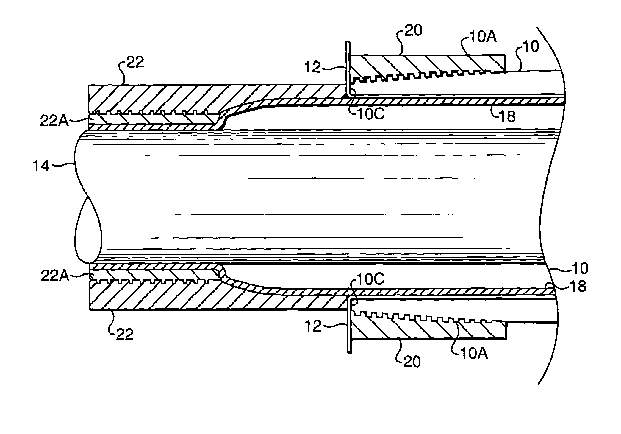
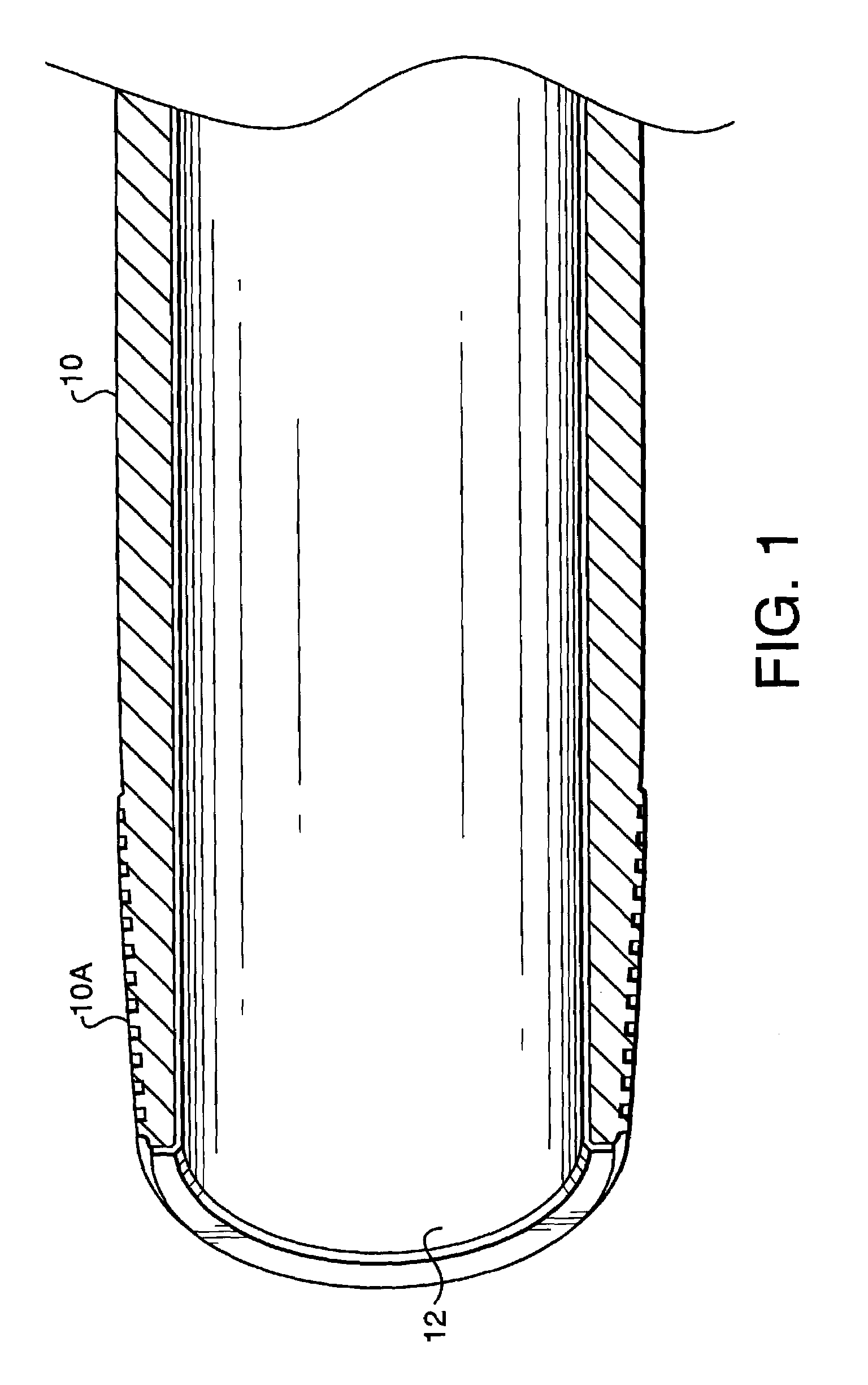
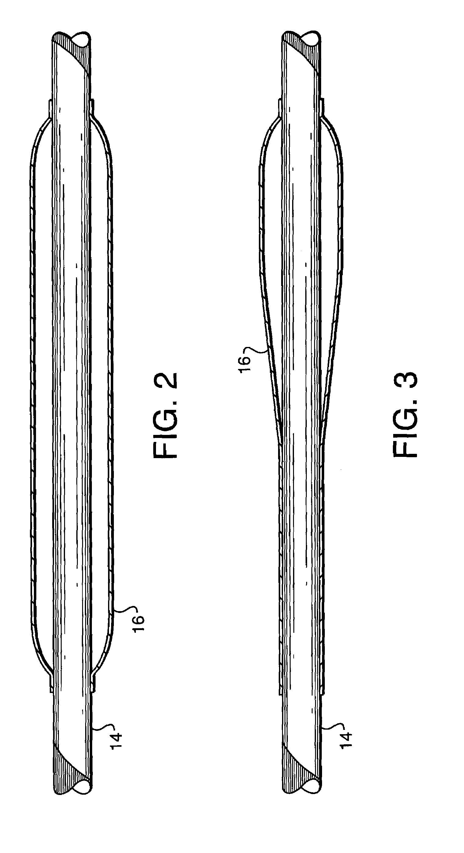
[0027]A preferred embodiment for a composite liner of the invention includes a fiber “preform”. The fiber can be glass, aramid, carbon / graphite or combinations thereof. The fiber can be woven or can be in the form of a needlefelt such as a product made by Textech, N. Monmouth, Me. Generally the preform is in the shape of a tube. The preform is impregnated with a resin such as high-ductility amine-cured epoxy. The resin-impregnated preform is impressed onto the inner wall of a joint of oilfield pipe such as casing or tubing, is formed and bonded to the ends of the joint and is then cured in place on the inner surfaces of the joint of oilfield pipe, such as tubing or casing.

[0028]The preferred embodiment of the composite liner will provide excellent resistance to oilfield chemicals, good performance in hot / wet environments prevalent in oilfield applications, and high working temperatures. The composite liner will have low void content, preferably less than about 3%, as voids in a comp...


PUM

PropertyMeasurementUnit
elongationaaaaaaaaaa
temperaturesaaaaaaaaaa
thicknessaaaaaaaaaa

Abstract

A composite lined tube is disclosed having end couplings. The tube includes a resin impregnated fiber preform pressed progressively along an inner wall of the tube. The tube may further include an inflatable bladder inserted into the tube. The bladder is adapted to inflate along a length thereof on application of increasing pressure to the interior of the bladder. The bladder has disposed on its exterior surface the fiber preform impregnated with resin, which is adapted to fit within the tube. The bladder is then inflated along its length by applying increasing pressure to the bladder. The preform is clamped to a shoulder of one of the couplings at another end of the tube, and the end of the preform is trimmed to conform to the shoulder. Pressure is maintained in the bladder while curing the resin.

Description

[0001]This application is a divisional application of Ser. No. 09 / 434,053 filed Nov. 4, 1999, now U.S. Pat. No. 6,596,121, which issued Jul. 22, 2003.BACKGROUND OF INVENTION[0002]1. Field of the Invention[0003]The invention generally relates to fiber-reinforced composite conduits or tubes and methods for making such conduits or tubes. More particularly, the invention is related to composite pipe liner for oilfield tubular goods which have improved corrosion resistance, and methods for making such lined tubular goods.[0004]2. Background Art[0005]Oilfield tubular goods are threaded segments or “joints” of seamless pipes made from steel and are used in oil and gas well extraction and injection applications among other applications. Oilfield tubular goods are often exposed to fluids which cause corrosion. It is known in the art to try to control this corrosion by making the tubular joints from corrosion-resistant alloy (“CRA”), such as stainless steels or nickel-based alloys, or by addi...

Claims


Application Information

Patent Timeline
03 Oct 2006
Publication
US7114751B2
IPC
F16L55/00; B32B37/00; B29C33/50; B29C63/34; B29C70/44
CPC
B29C33/505; B29C63/346; B29C70/446; B29C2793/00
Inventors
REYNOLDS, JR., HARRIS A.