Printed-circuit board with fuse

a printed circuit board and fuse technology, applied in the direction of printed circuit, programmable/customizable/modifiable circuit, non-metallic protective coating application, etc., can solve the problems of reducing working efficiency, bulky fuse b>110/b>, and different fuse size from electronic parts b>11, etc., to achieve simple and inexpensive means

Inactive Publication Date: 2006-10-03
ROHM CO LTD
View PDF32 Cites 35 Cited by
  • Summary
  • Abstract
  • Description
  • Claims
  • Application Information

AI Technical Summary

Benefits of technology

[0007]The present invention has been conceived in light of the above situation, and it is an object thereof to provide a compact, fused printed wiring board by a simple and inexpensive means.

Problems solved by technology

A problem encountered with the conventional printed wiring board 101 described above was that the size of the fuse 110 was different from that of the electronic parts 11.
Consequently, some chip mounters for mounting the electronic parts 11 were unable to mount the fuse 110 on the insulating substrate 102, which meant that the fuse 110 had to be mounted manually, and this lowered the working efficiency.
Furthermore, the fuse 110 tended to be bulky because it had the package 111.
This hindered efforts at reducing the size of the printed wiring board 101.

Method used


Image

  • Printed-circuit board with fuse
  • Printed-circuit board with fuse
  • Printed-circuit board with fuse

Examples


first embodiment

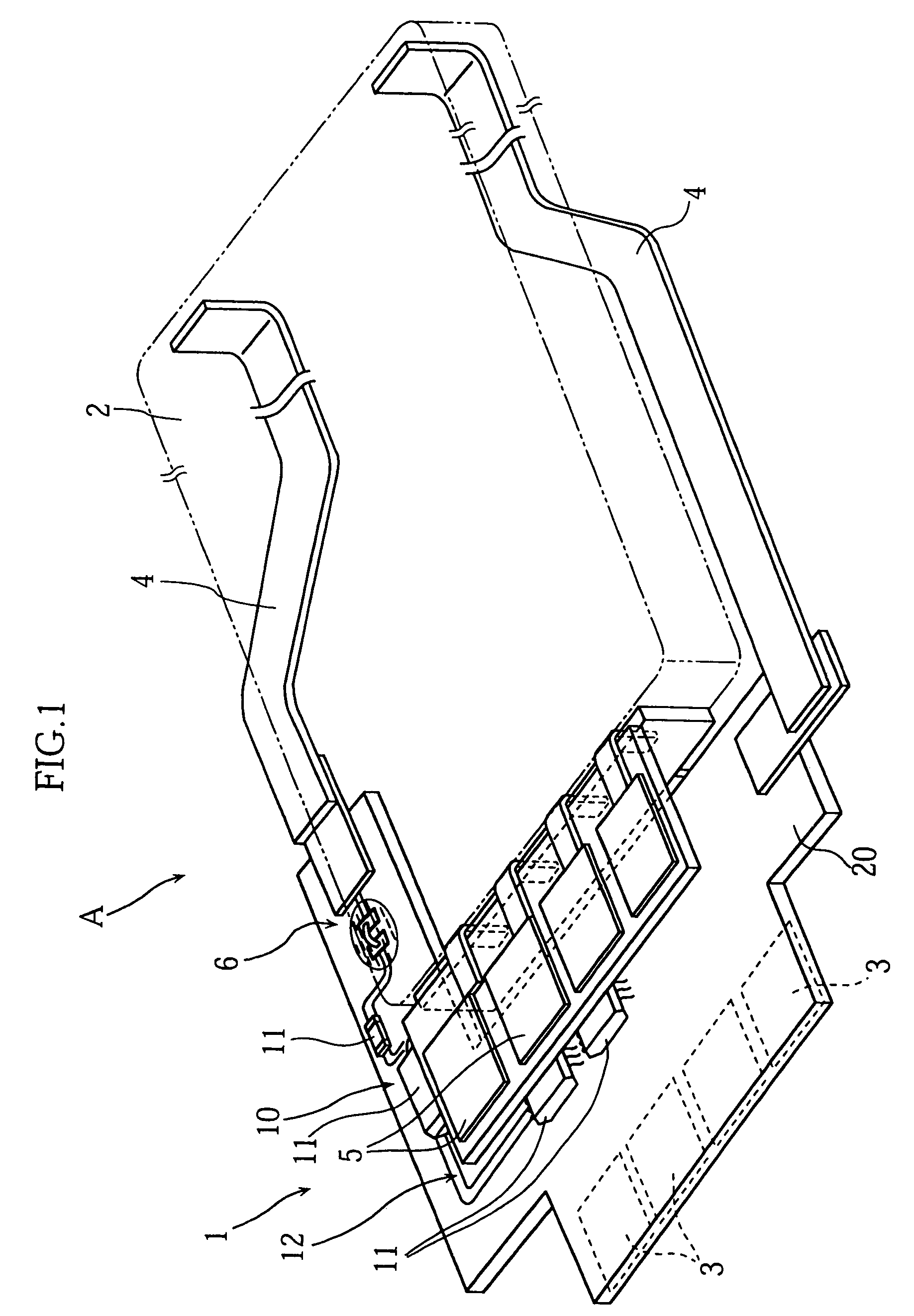
[0038]FIG. 1 illustrates the main portion of a battery pack A that incorporates the printed wiring board 1 pertaining to the present invention. The battery pack A is equipped with a chargeable battery 2, which can be used, for instance, as a drive power source of a cellular telephone. The battery 2 is connected via two metal conductors 4 to a wiring pattern 12 (only partially depicted) formed on the wiring board 1. The wiring board 1 includes a substrate 20 composed of an insulating material (such as glass epoxy), and on the back side thereof are formed four terminals 3 for receiving the supply of electricity from an external power source and charging the battery 2. Four terminals 5 for supplying electricity from the battery 2 to the outside are provided on the top side of the wiring board 1.

[0039]A protection circuit 10 for preventing excess current from flowing into the battery 2 during charging is provided to the wiring board 1. The protection circuit 10 consists of transistors o...

second embodiment

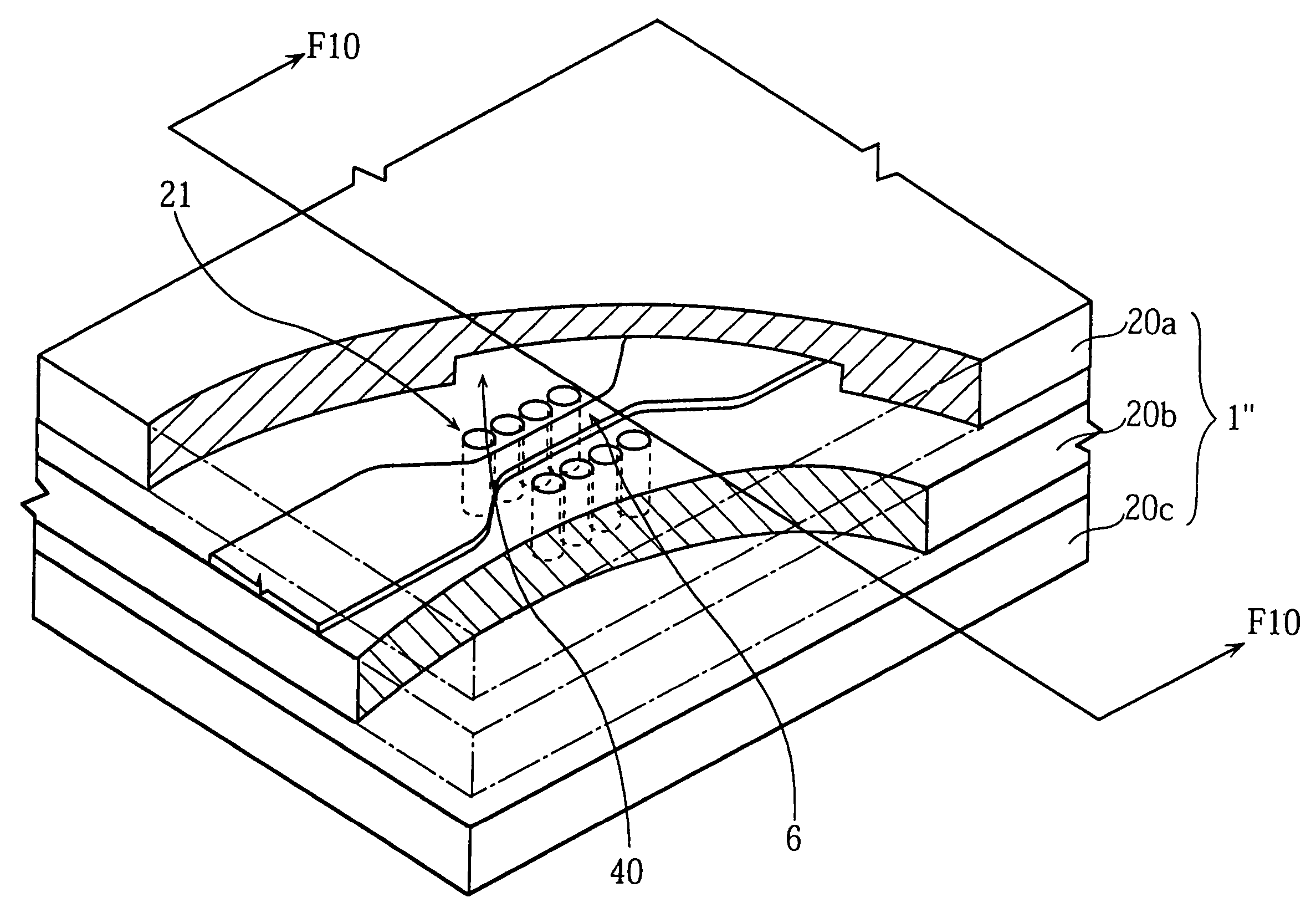
[0045]FIG. 5 the main portions of a battery pack A1 that incorporates the printed wiring board 1′ pertaining to the present invention. Just as with the printed wiring board 1 described above, the printed wiring board 1′ in FIG. 5 includes an insulating substrate 20, over which four charging terminals 3, a fuse 6′, electronic parts 11, a wiring pattern 12, and so forth are provided.

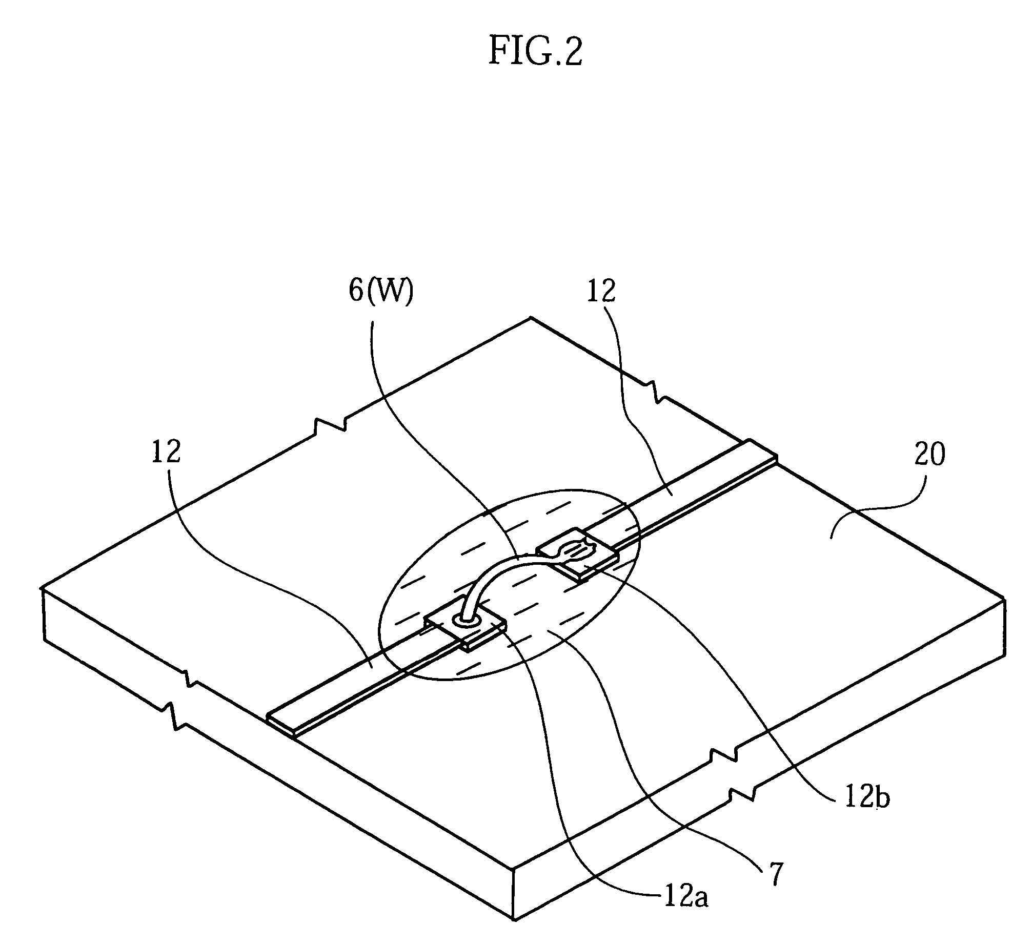
[0046]As shown in FIG. 6, the fuse 6′ is realized by making part of the wiring pattern 12 relatively narrow in width. The wiring pattern 12 including the fuse 6′ can be formed subjecting the conductor film formed on the substrate 20 to etching in a specific pattern by photolithography.

[0047]With the second embodiment of the present invention, a plurality of through holes 21 are formed in the substrate 20 in the vicinity of the fuse 6′. The illustrated through holes 21 (eight of them in FIG. 6) are divided into two equal groups, and sandwich the fuse 6′ on either side. With this configuration, the air insid...

fourth embodiment

[0051]FIGS. 11 and 12 illustrate a fuse 6″ provided to a printed wiring board 1′″ pertaining to the present invention. The printed wiring board 1′″ includes first to fourth substrates 21a to 21d, and a specific wiring pattern is formed on the upper and / or lower side of each of these substrates. These wiring patterns are electrically connected to each other via through holes provided in the substrates 21a to 21d (see 13 in FIG. 15).

[0052]As shown in FIG. 12, the fuse 6″ is provided to the third substrate 21c. The fuse 6″ is exposed to the outside via through holes 71 consisting of openings 71a to 71d formed in the substrates 21a to 21d, respectively.

[0053]The fuse 6″ is provided as part of the wiring pattern formed on the third substrate 21c, and bridges the opening 21c. The fuse 6″ can be formed by first forming the specific wiring pattern on the substrate 21c, and then making the opening 21c in the substrate 21c. An etching technique that acts only on the substrate 21c, for example...


PUM


Abstract

A printed wiring board includes a substrate (20) on which a wiring pattern (12) has been formed, and a fuse (6) provided on the substrate (20). One end of the fuse (6) is directly connected to a first pad (12a) of the wiring pattern (12), and the other end of the fuse (6) is directly connected to a second pad (12b) of the wiring pattern (12). The fuse (6) is covered by a protective material (7).

Description

[0001]This application is a division of application Ser. No. 10 / 221,616, filed Sep. 12, 2002 now abandoned, which application is incorporated herein by reference.TECHNICAL FIELD[0002]This invention relates to a printed wiring board equipped with a fuse.BACKGROUND ART[0003]Printed wiring boards equipped with fuses for circuit protection have been used in the past in a wide variety of electronic devices. FIG. 16 of this application illustrates a printed wiring board 101 used in a battery pack for a cellular telephone. This printed wiring board 101 is equipped with an insulating substrate 102, on which a specific wiring pattern (not shown) is formed. Also, a protection circuit 10 and a fuse 110 are mounted on this insulating substrate 102. The protection circuit 10 serves to prevent the overcharging of a battery 2, and consists of transistors or various other such electronic parts 11. The fuse 110 works as a failsafe device in the event that the protection circuit 10 should not functio...

Claims


Application Information

Patent Timeline
Patent Type & Authority Patents(United States)
IPC IPC(8): H01H85/08H01H85/48H01H85/00H01H85/041H01H85/046H01H85/46H05K1/00H05K3/28H05K3/46
CPCH01H85/0411H01H85/046H05K1/0293H01H85/0047H01H85/463H01H2069/027H01H2085/0275H05K1/0272H05K3/28H05K3/4611H05K3/4697H05K2201/0305H05K2201/0394H05K2201/062H05K2201/09063H05K2201/09727H05K2201/0989H05K2201/10037H05K2201/10181H05K2203/049
Inventor NISHIMURA, KOHSHINAKAMURA, SATOSHISUZUKI, SAIZOU
Owner ROHM CO LTD
Why Eureka
Try Eureka