Eureka AIR delivers breakthrough ideas for toughest innovation challenges, trusted by R&D personnel around the world.

Frequency hopping spread spectrum communication system

a technology of spread spectrum and communication system, which is applied in the direction of transmission, electrical equipment, network planning, etc., can solve the problems of limited devastating effect on system performance, and limited effect of narrow band interference in a particular region, etc., and achieve the effect of enhancing the performance of the individual performance (i) abov

Inactive Publication Date: 2006-10-03
NOKIA TECHNOLOGLES OY
View PDF8 Cites 18 Cited by
  • Summary
  • Abstract
  • Description
  • Claims
  • Application Information

AI Technical Summary

Benefits of technology

[0012]Thus, the system of the present invention is able to keep track of those frequency bands in the hopping sequence which have previously been most susceptible to interference.
[0013]By doing so, the system of the present invention can take steps to avoid those frequency bands which have in the past been most susceptible to interference and so, in the immediate future, are most likely to be noisy. As a result, the system's own performance ((i) above) is enhanced, because it does not have to waste its efforts trying to communicate in a frequency band where its transmission is likely to be disrupted. Also, from the viewpoint of neighbouring systems ((ii) above), the system of the present invention is sociable in its use of spectrum, because having identified when a particular frequency band is persistently noisy, and therefore perhaps is being used, it can avoid that frequency band for the near future and thereby not kill the data traffic of a neighbouring communication system—if there is one.

Problems solved by technology

Thus, because the frequency hopping spread spectrum system is continually hopping between parts of the spectrum, the effect of narrow band interference in a particular region is limited.
Persistent interferers present two distinct problems to this kind of system.
Although the use of a frequency hopping spread spectrum system per se limits the degradation in system performance caused by a persistent interferer, the effect on system performance can be significant, especially in the presence of several persistent interferers.
The presence of a nearby frequency hopping spread spectrum regularly hopping into the region of the spectrum used by the WLAN during the transmission of a large packet can have a devastating effect on the WLAN's performance.

Method used


Image

  • Frequency hopping spread spectrum communication system
  • Frequency hopping spread spectrum communication system
  • Frequency hopping spread spectrum communication system

Examples


Embodiment Construction

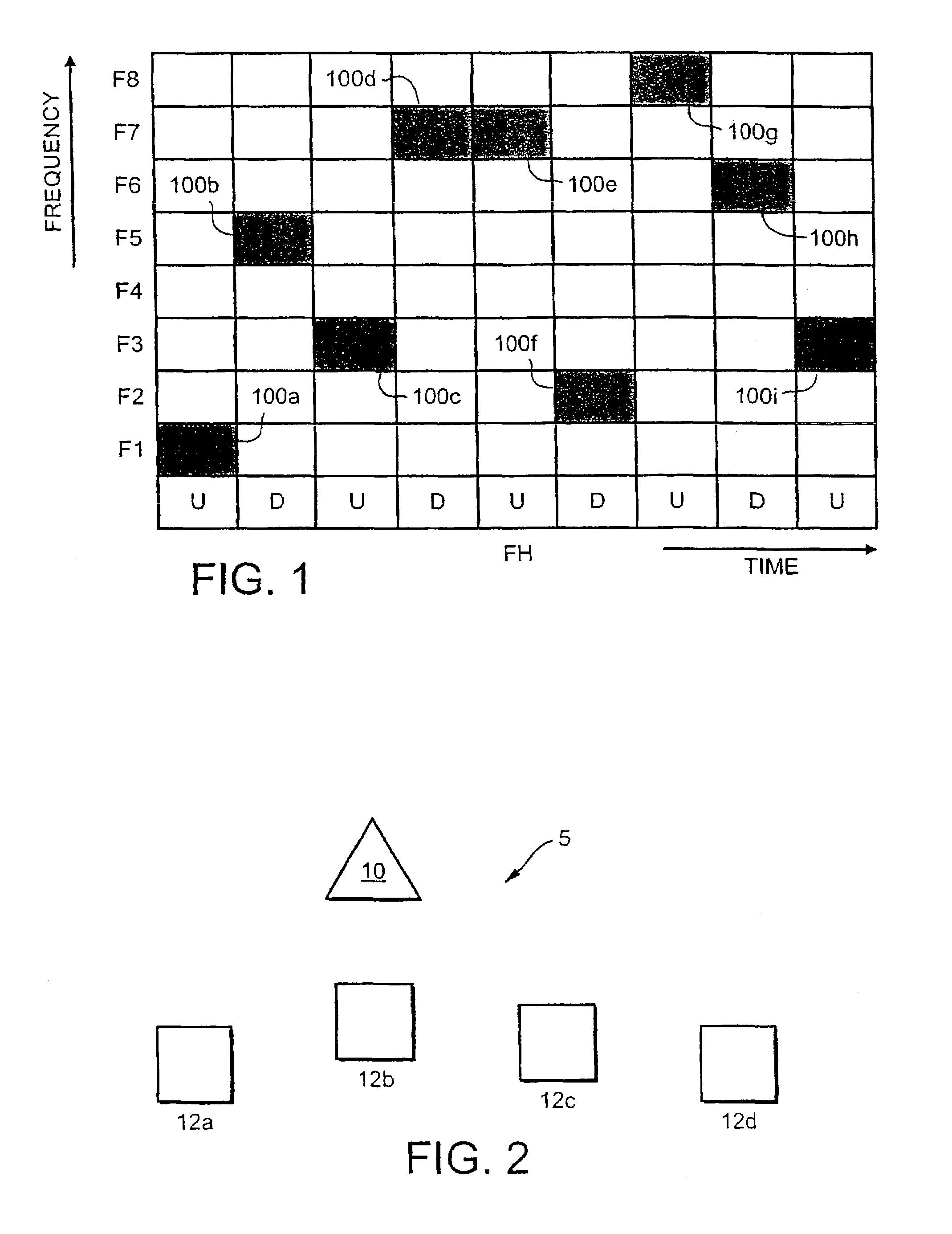
[0028]FIG. 2 shows a frequency hopping spread spectrum system / network, generally designated 5, operating in the ISM band. The system 5 comprises five nodes: a node 10 serves as the master node and the other four nodes serve as slave nodes 12a, 12b, 12c and 12d. These devices are lower power RF devices, preferably operating in accordance with the Bluetooth protocol. Within the system 5, communication takes place, bidirectionally, between the master node 10 and any of the slave nodes 12a, 12b, 12c and 12d. No communication takes place directly between the slave nodes themselves.

[0029]Each node 10,12 is identical having the same hardware and the same software enabling it to be operable to act as a master node or a slave for a given network, or possibly acting as the master node for a first network while simultaneously acting as a slave node for a second network.

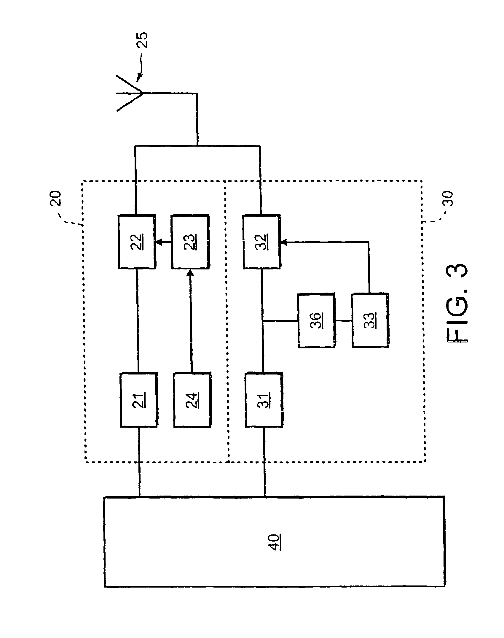
[0030]In more detail, referring to FIG. 3, each node 10,12 comprises a transmitter 20, a receiver 30 and a control processor 4...


PUM


Abstract

A method of operating a spread spectrum radio communication system comprising a central node and a dependent node which communicate over a frequency hopping channel. The dependent node compiles interference information for the channel and, at intervals, transmits the interference information to the central node. The central node, based on the interference information received from the dependent node, creates a black list of worse-performing frequency bands in the channel.

Description

CROSS-REFERENCE TO RELATED APPLICATIONS[0001]This application is a National Phase application based on International Application No. PCT / IB99 / 02085, filed on Dec. 22, 1999.FIELD OF THE INVENTION[0002]The present invention relates to a frequency hopping spread spectrum communication system.BACKGROUND OF THE INVENTION[0003]In most countries, the part of the spectrum commonly known as the Industry Scientific Medicine or ISM band (in the region of 2.4 GHz) is largely unregulated, meaning that no license is needed to make electromagnetic transmissions in this band.[0004]In this unruly part of the spectrum, frequency hopping spread spectrum systems have been found to have good performance. In these systems, the carrier frequency of a modulated information signal changes or hops periodically to another (or possibly the same) frequency of a set of possible frequencies called the hop set. The hopping sequence is governed by the spreading code. FIG. 9 shows the time / frequency occupancy of an ...

Claims


Application Information

Patent Timeline
Patent Type & Authority Patents(United States)
IPC IPC(8): H04B1/69H04B1/713H04B7/26H04W16/04H04W16/12
CPCH04B1/715H04W16/04H04B2001/7154H04W16/12
Inventor SIVAKUMAR, TATIKONDA
Owner NOKIA TECHNOLOGLES OY
Why Eureka
Eureka Blog
Learn More