Optical signal regenerator

a technology of optical signal and regenerator, which is applied in the direction of multiplex communication, pulse technique, instruments, etc., can solve the problems of inability to gain sufficient pulse extinction ratio of conventional optical pulse multiplexers, and difficulty in stably generating high-speed optical clocks not only in technical aspects but also in terms of production costs

Inactive Publication Date: 2006-10-03
KDDI CORP
View PDF4 Cites 2 Cited by
  • Summary
  • Abstract
  • Description
  • Claims
  • Application Information

AI Technical Summary

Problems solved by technology

It is difficult to obtain a high-speed optical gate element.
It is also difficult to stably generate a high-speed optical clock not only for technical aspects but also in terms of production costs.
However, a conventional optical pulse multiplexer is unable to gain sufficient pulse extinction ratios and it is yet unsatisfactory in respect of stability, quality, and costs.
However, it is difficult to obtain such a polarization modulating element that operates at high-speed and has such functions described above.

Method used


Image

  • Optical signal regenerator
  • Optical signal regenerator
  • Optical signal regenerator

Examples


Embodiment Construction

[0014]Embodiments of the invention are explained below in detail with reference to the drawings.

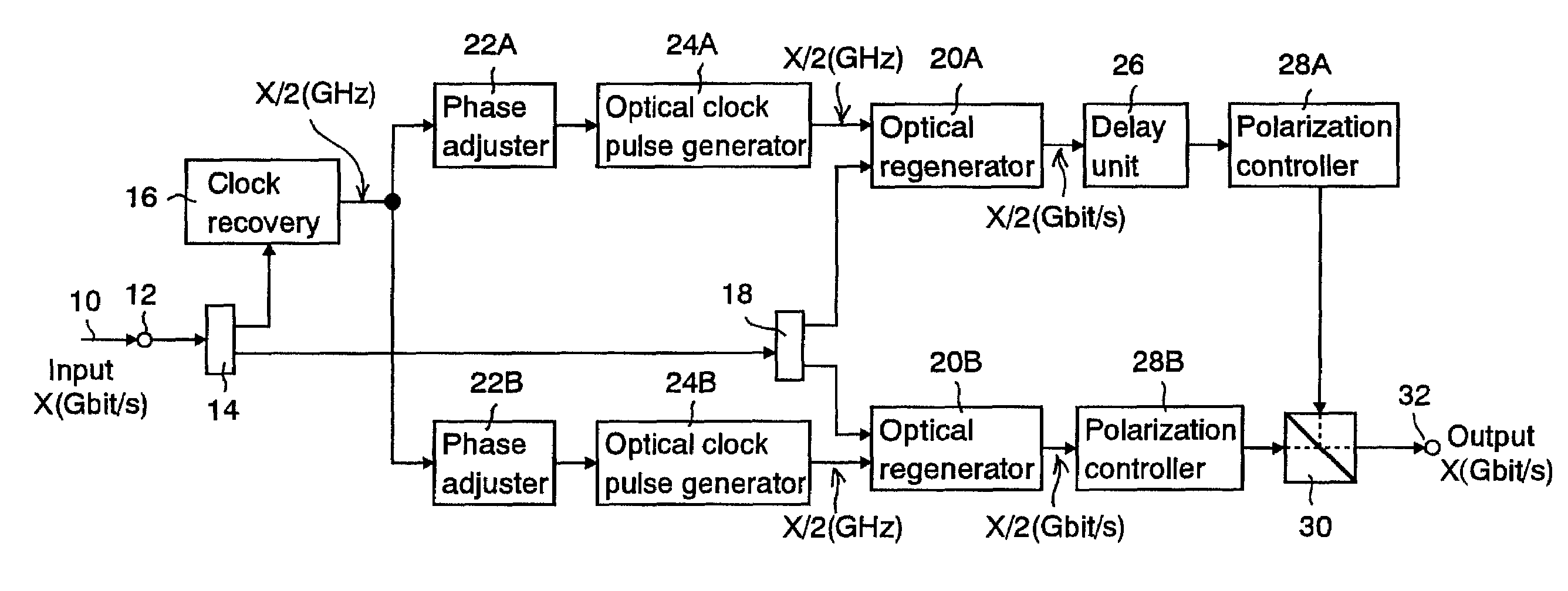
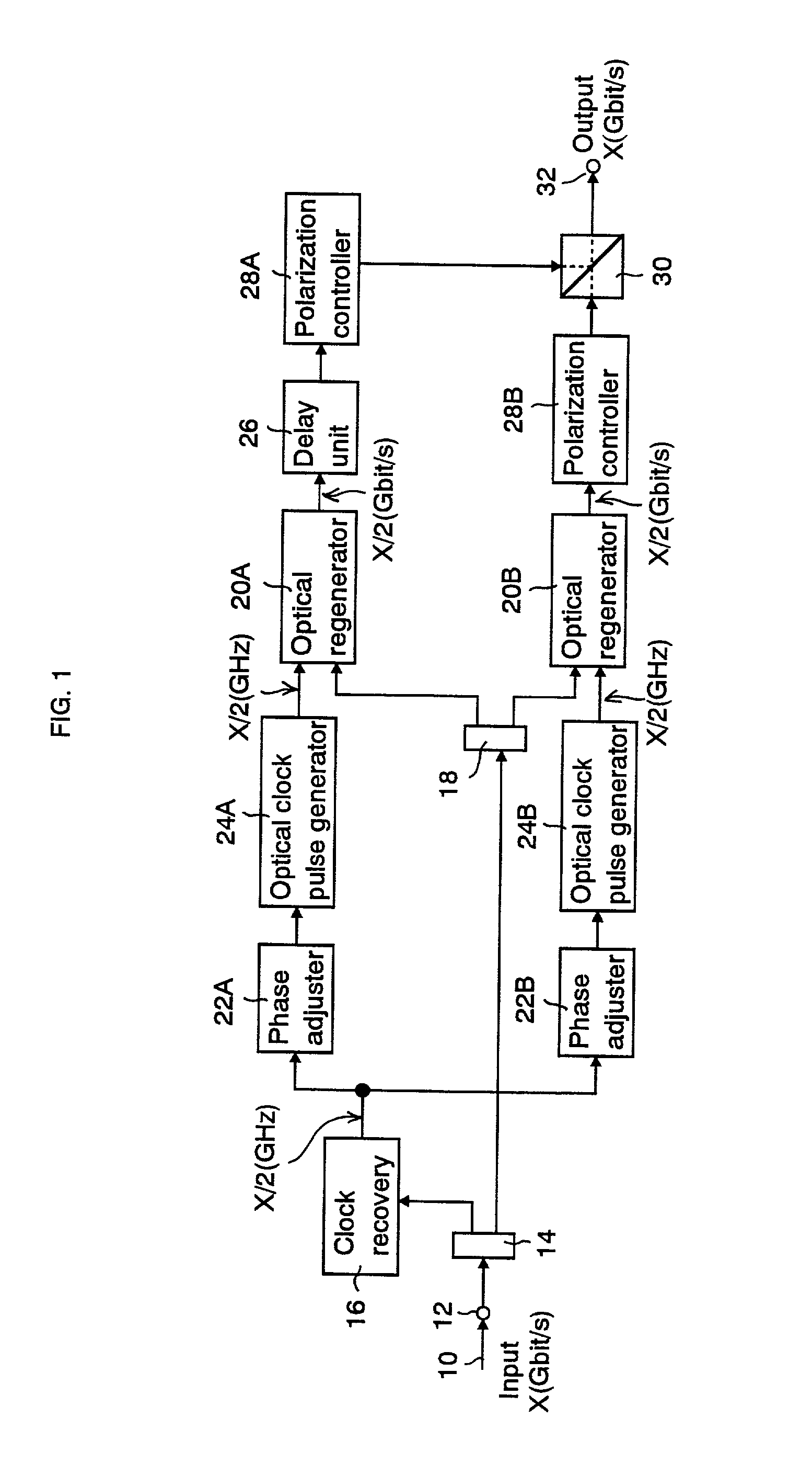
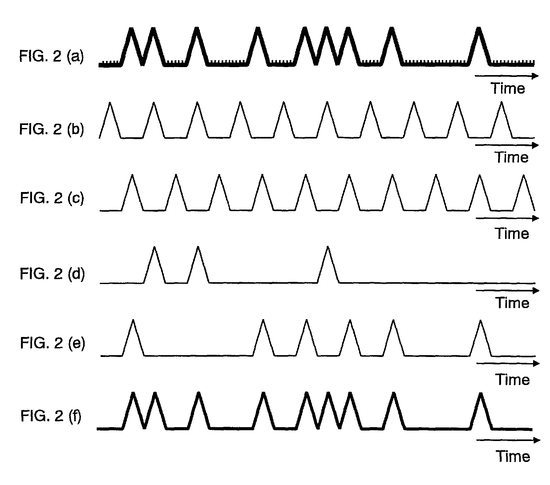
[0015]FIG. 1 shows a schematic block diagram of a first embodiment according to the invention. FIGS. 2(a)–(f) respectively shows a waveform of each part.

[0016]An optical pulse of X (Gbit / s) signal 10 enters an input terminal 12. FIG. 2(a) shows a waveform example of the optical pulse signal 10. For example, X is set to 40. An optical splitter 14 applies about 1 / 10 of the optical power of the optical pulse signal 10 from the input terminal 12 to a clock recovery circuit 16 and the rest to an optical splitter 18. The optical splitter 18 splits the input light into half and applies one portion to an optical regenerator 20A and the other to an optical regenerator 20B.

[0017]The clock recovery circuit 16 regenerates an electric clock signal of X / 2 (GHz) out of the optical pulse from the optical splitter 14. Phase adjusters (delay circuits) 22A and 22B adjust phase of the electric clock signal f...


PUM

PropertyMeasurementUnit
frequencyaaaaaaaaaa
opticalaaaaaaaaaa
frequenciesaaaaaaaaaa

Abstract

The present invention regenerates optical signals in an intact optical state according to a low-speed optical clock. In one embodiment, an optical splitter applies a portion of optical pulse signals to a clock recovery circuit and the rest to an optical splitter. The optical splitter applies half of the input signal to an optical regenerator and the rest to another optical regenerator. The clock recovery circuit regenerates an electric clock signal with half the frequency of the input optical pulse and applies the clock to an optical clock pulse generator. The optical clock pulse generator generates an optical clock signal with half the frequency of the input optical pulse whose phase matches with that of the optical signal at the optical regenerator. An optical regenerator regenerates the optical signal from the optical splitter in an intact optical state. A polarization combiner combine the optical signals from the optical regenerators in mutually orthogonal polarization.

Description

CROSS REFERENCE TO RELATED APPLICATIONS[0001]This application is based upon and claims the benefit of priority from the prior Japanese Patent Application No. 2001-184332, filed Jun. 19, 2001, the entire contents of which are incorporated herein by reference.FIELD OF THE INVENTION[0002]This invention relates to an optical signal regenerator to regenerate optical signals in an intact optical state.BACKGROUND OF THE INVENTION[0003]In a conventional optical signal regenerator, especially in a conventional optical signal regenerator to regenerate high-speed optical pulse signals as fast as 40 Gbit / s in an intact optical state, an optical clock pulse train synchronizing with an input optical signal pulse train is gated by the input optical signal pulse train. Owing to this operation, even if a pulse waveform of the input optical signal is distorted, each pulse waveform of output optical signals becomes almost identical to that of the optical clock pulse train.[0004]It is difficult to obta...

Claims


Application Information

Patent Timeline
Patent Type & Authority Patents(United States)
IPC IPC(8): H04B10/02H04B10/12H04B10/16H04B10/20H04J14/00G02F1/015H04B10/00H04B10/516H04B10/61
CPCH04B10/299
Inventor OTANI, TOMOHIROSUZUKI, MASATOSHI
Owner KDDI CORP
Why Eureka
Try Eureka