Slotting cutter and cutting insert therefor

a cutting insert and slotting cutter technology, applied in the field of slotting cutters, can solve the problems of inferior machining results, uneven loading of cutting inserts, and risk of incorrect assembly of cutting inserts,

Inactive Publication Date: 2006-10-10
HOGANAS AB +1
View PDF10 Cites 38 Cited by
  • Summary
  • Abstract
  • Description
  • Claims
  • Application Information

AI Technical Summary

Problems solved by technology

In particular, in previously known slotting cutters there is a risk for incorrect assembly of the cutting inserts, on one hand inasmuch as the positional accuracy may become mediocre, and on the other hand inasmuch as the cutting inserts may be indexed in a wrong way.
Namely, if two cutting inserts following each other along the periphery of the cutting disc would be mounted in an incorrect way, the cutting inserts will be loaded unevenly; something which may lead to inferior machining results and even breakdowns.
However, in this case the cutting inserts are not dismountable and indexable, and therefore the risk for unintentional incorrect assembly cannot arise.

Method used


Image

  • Slotting cutter and cutting insert therefor
  • Slotting cutter and cutting insert therefor
  • Slotting cutter and cutting insert therefor

Examples


Embodiment Construction

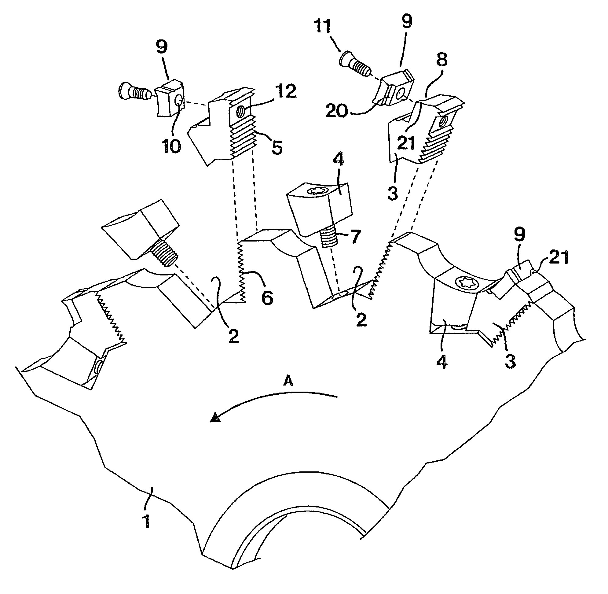
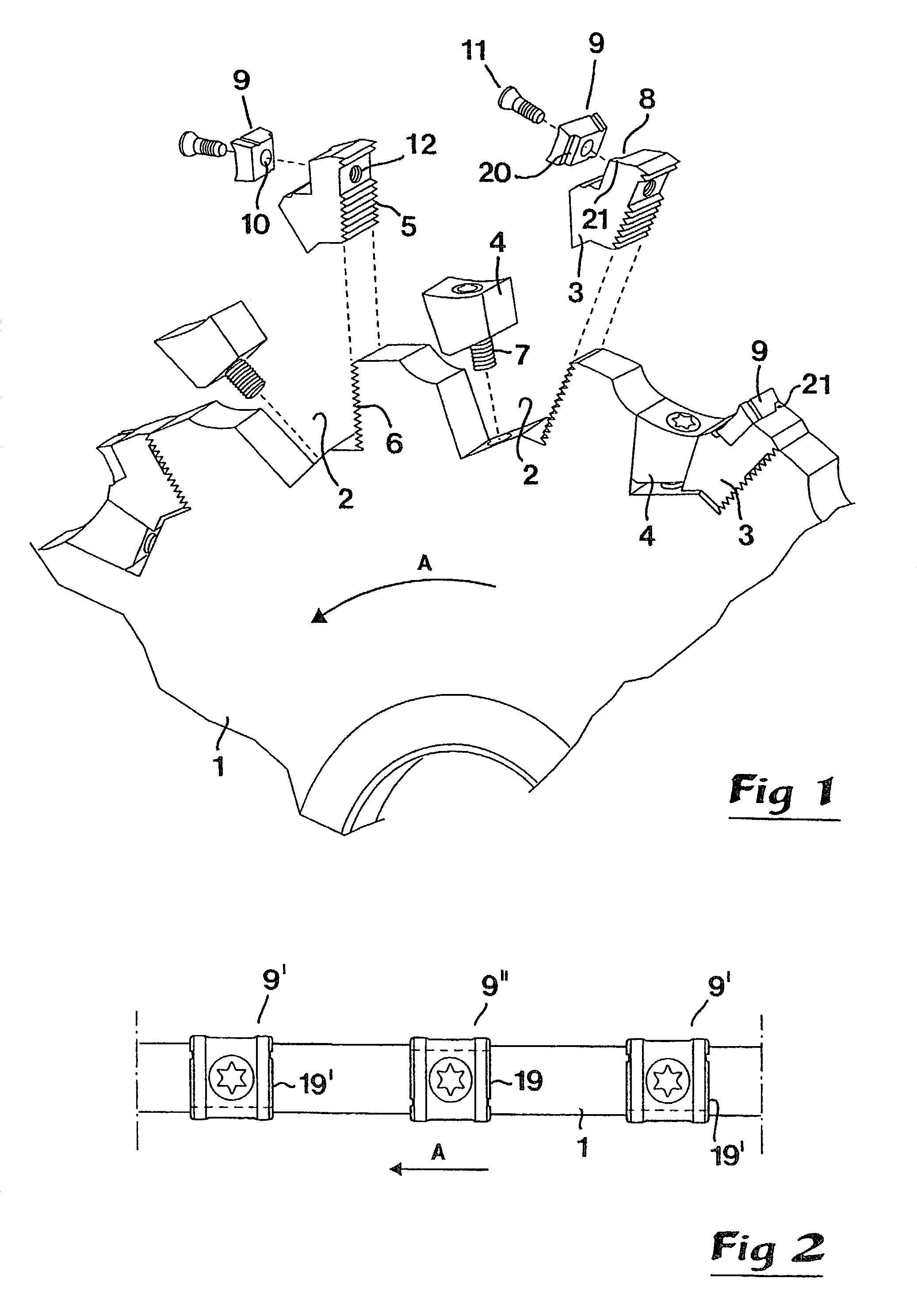
[0023]In FIG. 1, a slotting cutter is illustrated which includes a circular disc 1 being rotatable around a central axis of rotation (not shown), more precisely in the direction of the arrow A. Along the periphery of the disc, a plurality of tangentially spaced chip channels 2 are formed, each one of which houses a cassette 3, as well as a wedge 4 for fixing of the cassette. In order to secure the cassette 3 reliably, the same is formed with a serration 5 cooperating with a corresponding serration 6 in a rear wall of the chip channel. The wedge 4 is tightenable by means of a screw 7. In each cassette 3, a seat 8 is formed for the receipt of a cutting insert 9. In said cutting insert, there is a central hole 10 for a fixing screw 11, which is tightenable in a threaded hole 12 in the cassette.

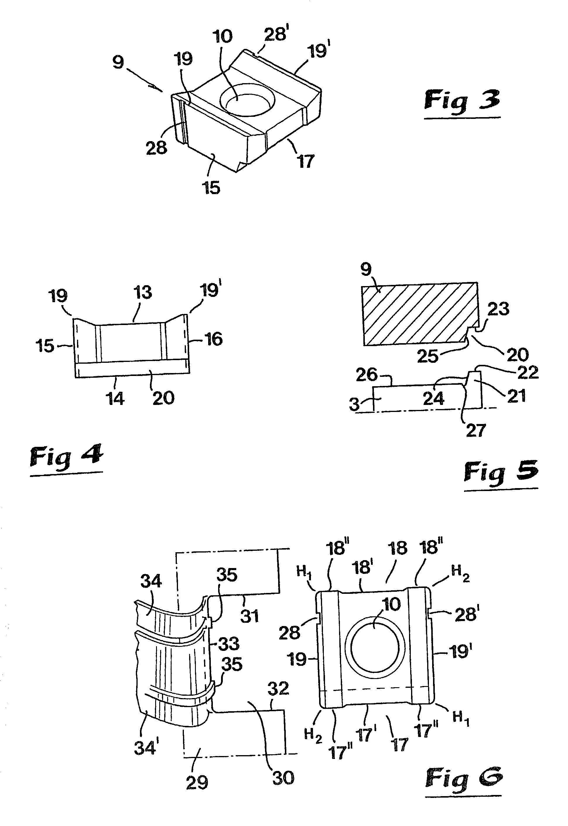
[0024]As is best seen in FIGS. 3–5, the cutting insert 9 consists of a flat body having a quadrangular basic shape which is delimited by a top side 13, a bottom side 14, first and second end surf...


PUM

PropertyMeasurementUnit
angle of inclinationaaaaaaaaaa
thicknessaaaaaaaaaa
axis of rotationaaaaaaaaaa

Abstract

A slotting cutter includes a circular disc having an outer periphery along which a plurality of chip channels are formed which define respective seats for receiving respective index able cutting inserts. Each insert includes a planar bottom side. Either the seat or the bottom side has a male locator portion, and the other of the seat and the bottom side has a female locator portion which receives the male locator portion to define therewith and insert-locating structure. The male and female locator portions are offset laterally from a center plane of the insert oriented perpendicular to an axis of rotation of the disc. Alternating ones of the insert-locating structures are disposed on respective opposite sides of the center plane.

Description

TECHNICAL FIELD OF THE INVENTION[0001]In a first aspect, this invention relates to a slotting cutter of the type that comprises a circular disc along the periphery of which a plurality of tangentially, spaced chip channels are formed, which house seats for indexable cutting inserts having a width which is larger than the thickness of the disc in order that the inserts can mill out a groove that is delimited by two parallel side surfaces and a bottom, during the milling of a workpiece, the cutting inserts having means for dividing the material which is separated from the bottom of the cutting groove into two or more partial chips.[0002]Slitting cutters and slotting cutters should be considered as being the same.PRIOR ART[0003]Modern slotting cutters of the general type given above usually, make use of special cassettes for mounting the cutting inserts. Said cassettes are formed with a seat for the indexable cutting insert. as well as a serration for engagement with an analogous serra...

Claims


Application Information

Patent Timeline
Patent Type & Authority Patents(United States)
IPC IPC(8): B23D13/00B23C5/08B23C5/20B23C5/22
CPCB23C5/08B23C5/202B23C5/2226B23C2200/125B23C2200/126Y10T407/2202B23C2200/205B23C2220/36B23C2260/80Y10T407/1922Y10T407/1932B23C2200/128B23C5/2278
Inventor ASTROM, WILLY
Owner HOGANAS AB
Why Eureka
Try Eureka