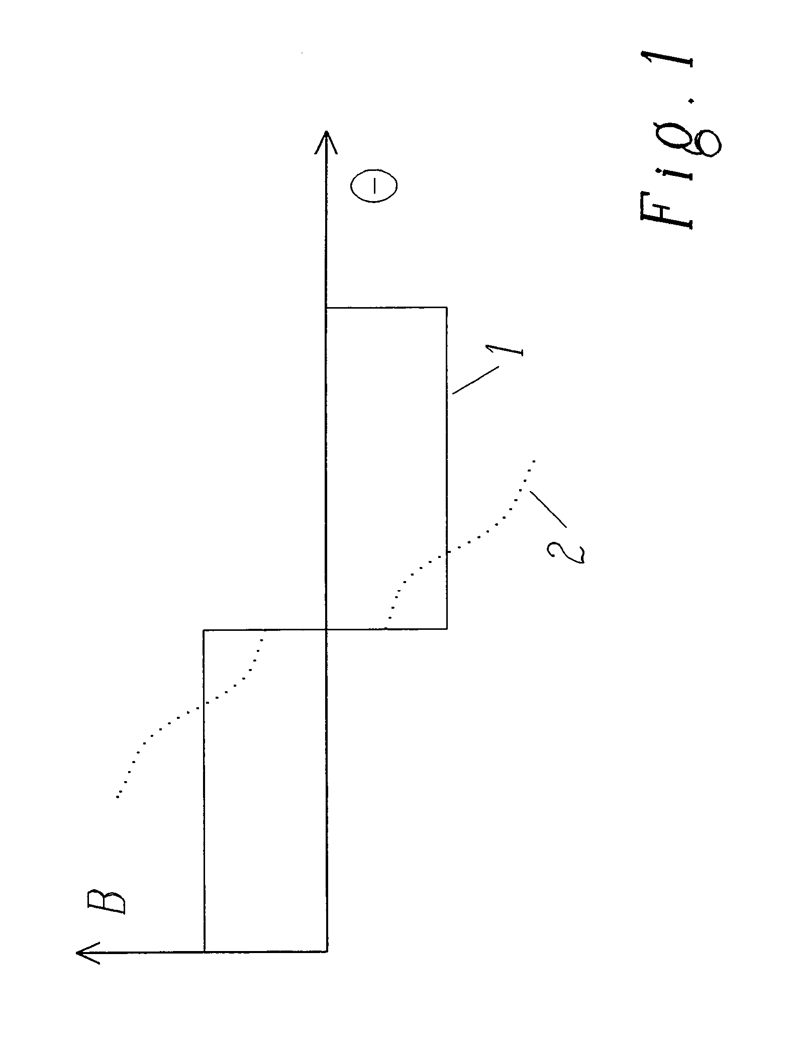
[0009]It is thus possible to cancel the armature reaction, which is also static, by means of simple auxiliary windings provided on the static outer core and by feeding these windings with a direct current such that the reaction field is cancelled. Almost full restoration of the ideal homogeneous field, as induced by a
static field winding (or by permanent
magnet), which is present when the rotor is not rotating is possible when using the proposed topology. The design of the windings can e.g. be realised by using simple bar technology allowing a cheap and easy manufacturing of this cancellation means for the armature reaction.
[0010]According to a first preferred and particularly simple and elegant embodiment of the invention, the geometry of the auxiliary windings is the same as the one of the rotor. It has to be noted that the armature reaction induced by the rotor is basically given by the geometry of the conductors in the rotor and by the current flowing in these conductors. It is thus surprisingly easily possible, by adapting the geometry of the auxiliary winding to the geometry of the conductors of the rotor, to produce, by means of these auxiliary windings, a field of the same geometry as the armature reaction but with opposite sign which consequently efficiently cancels the armature reaction. To this end, preferentially the individual conductors of the windings are substantially equally fed with a direct current of opposite direction to the one induced in the conductors of the rotor when it is rotating. This is particularly useful if the rotor is a rotor of an exciter comprising means for rectifying the
alternating current induced in the conductors of the rotor, as in this case the armature reaction can have particularly detrimental effects on the diodes.
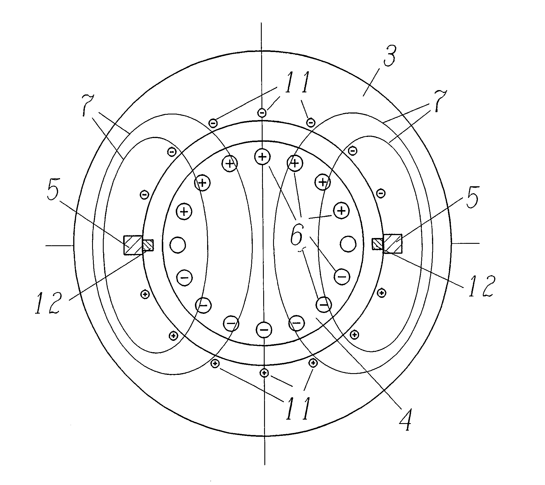
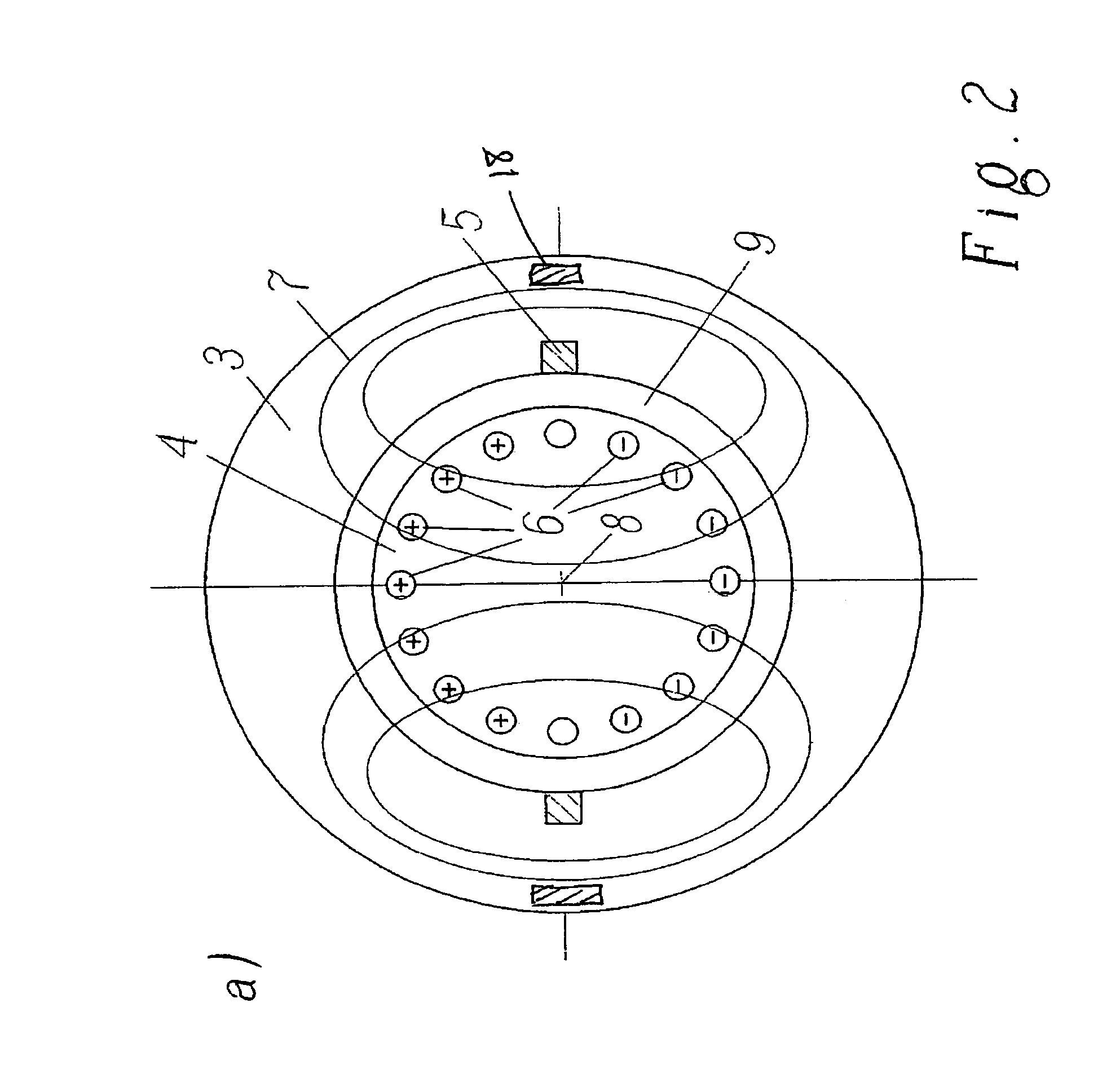
[0011]According to another preferred embodiment of the present invention, the auxiliary windings are substantially located on the inner surface of the static outer core and in the region of the rotor the auxiliary windings are arranged substantially parallel to the axis of the rotor. Locating the auxiliary windings as close as possible to the air gap makes sure that the field to cancel the armature reaction indeed has substantially the same geometry as the field generated by the conductors of the rotor. The larger the radial distance between the conductors of the rotor and the conductors of the auxiliary windings, the larger the geometrical differences between the two fields and the less perfect the cancellation of the armature reaction.
[0012]According to still another preferred embodiment of the invention, the same number of individual conductors of the auxiliary windings are provided as there are conductors on the rotor, wherein these individual conductors of the auxiliary windings are evenly distributed circumferentially around the air gap. In particular if the rotor is also having a design with conductors evenly distributed circumferentially about its circumference, such an auxiliary winding almost perfectly reproduces the geometry of the armature reaction and is thus capable of cancelling it very efficiently.
[0013]Control of the current fed through the conductors of the auxiliary windings can be effected by a
control unit which uses parameters like the speed of rotation, the induced direct current /
voltage in the rotor, and / or the direct current used to induce the
static field on the static outer core to regulate the current to cancel the armature reaction. However, in particular during transients, that is in situations where the
static field is increased or decreased (e.g. for controlling the direct current fed to the rotor of the generator), the current flowing in the conductors of the rotor cannot be derived from the current fed through the winding to induce the static field or from the direct current generated by the rotor. According to another preferred embodiment of the present invention, it is therefore proposed to provide at least one sensor to measure the armature reaction and to control the current fed through the auxiliary windings in response to the
signal generated by this sensor. This control allows to reduce peak loads on the diodes thus reducing the risk of breaking of the diodes.
[0017]Furthermore, the present invention relates to a brushless exciter for use with a synchronous generator for energising the field winding of its rotor, which is characterised in that it comprises a static outer core as it is described above. The cancellation of the armature reaction according to the invention proves to be particularly effective in case of use of a rotor for an exciter comprising at least two conducting bars aligned substantially parallel to the axis of the rotor, wherein said bars are connected on their first axial end to a collecting ring and wherein on their second axial end the bars are connected individually to two rings by means of diodes with
reversed polarity such that
alternating current induced in the conducting bars due to a static field is converted into a direct current (DC) in the two rings. Preferentially, the bars are arranged close to the
radial surface of the rotor, preferably as close as possible to the air gap between the rotor and the static outer core. In particular in case of so-called squirrel cage rotors with at least 4 conducting bars, preferably at least 8 conducting bars, and even more preferably 16 conducting bars, all of which conducting bars are evenly distributed along the circumferential radial angle of the rotor, the cancellation can be effectively applied due to the fact that the geometry of the armature reaction can be substantially reproduced and cancelled by such auxiliary windings. This is particularly necessary in case of speeds of operation of 6000 to 8000 rotations per minute thereby inducing a direct current in the two rings of the rotor of more than 2000
Ampere, preferably inducing a direct current of more than 10000
Ampere.



