Motor phase current measurement using a single DC bus shunt sensor

a shunt sensor and motor technology, applied in the direction of measurement devices, control systems, instruments, etc., can solve the problems of parasitic torque ripple components at various frequencies, deviations from pure sinusoidal back emf and current waveforms, and typical power requirements of electric power steering

Active Publication Date: 2006-10-10
STEERING SOLUTIONS IP HLDG +1
View PDF6 Cites 35 Cited by
  • Summary
  • Abstract
  • Description
  • Claims
  • Application Information

AI Technical Summary

Problems solved by technology

Therefore, electric power steering typically requires power only on demand.
However, due to practical limitations of motor design and controller implementation, there are always deviations from pure sinusoidal back EMF and current waveforms.
Such deviations usually result in parasitic torque ripple components at various frequencies and magnitudes.

Method used


Image

  • Motor phase current measurement using a single DC bus shunt sensor
  • Motor phase current measurement using a single DC bus shunt sensor
  • Motor phase current measurement using a single DC bus shunt sensor

Examples


Embodiment Construction

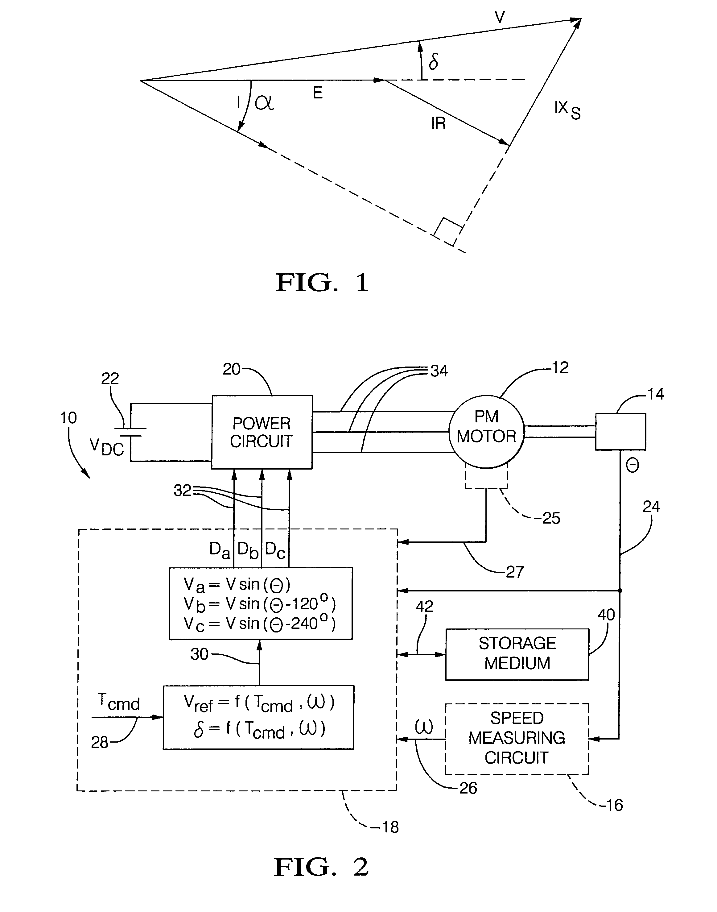
[0031]Referring now to the drawings in detail, FIG. 2 depicts a permanent magnet (PM) motor system where numeral 10 generally indicates a system for controlling the torque of a sinusoidally excited PM motor 12. The system includes a rotor position encoder 14, speed measuring circuit 16, controller 18, power circuit or inverter 20 and power source 22.

[0032]In the scheme depicted, the torque of the motor 12 is controlled using voltage mode control. Instead of controlling the torque producing current, the controller determines the voltage required for producing the desired torque based on motor equations. The voltage mode control method is based on electric machine operation phasor diagram as shown in FIG. 1. Under steady state operating condition, the voltage phasor {overscore (V)}, back EMF phasor Ē and current phasor Ī of a sinusoidally excited PM motor are governed by:

{overscore (V)}=Ē+ĪR+jĪXs  (1)

where R is the winding resistance, Xs is the phase reactance which is equal to the pr...


PUM


Abstract

A method and system for obtaining motor current measurements from a DC bus current of an inverter that drives a pulse width modulated electric machine is disclosed. The method may include sensing a DC bus current in a sensor located on a bus of an inverter; sampling the DC bus current via an analog to digital converter wherein the sampling is controlled by sampling timing that is based on a pulse width modulation timing of the inverter; and determining three AC phase currents of the motor from the sampled DC bus current.

Description

BACKGROUND[0001]Most modern vehicles have power steering in which the force exerted by the operator on the steering wheel is assisted by hydraulic pressure from an electric or engine-driven pump. The force applied to the steering wheel is multiplied by the mechanical advantage of a steering gear. In many vehicles, the steering gear is a rack and pinion, while in others it is a recirculating ball type.[0002]Electric power steering has started to replace hydraulic power steering in some vehicles for fuel economy. One way this is accomplished is through the reduction or elimination of losses inherent in traditional steering systems. Therefore, electric power steering typically requires power only on demand. Commonly, in such systems an electronic controller is configured to require significantly less power under a small or no steering input condition. This dramatic decrease from conventional steering assist is the basis of the power and fuel savings. Electric power steering has several...

Claims


Application Information

Patent Timeline
Patent Type & Authority Patents(United States)
IPC IPC(8): G01R13/14
CPCG01R31/343H02M7/5395H02M2001/0009H02M1/0009
Inventor MIR, SAYEED A.FISHER, PAUL M.SHAFER, DANIEL W.UNDERWOOD, SAMUEL J.
Owner STEERING SOLUTIONS IP HLDG
Why Eureka
Try Eureka