Low-skew single-ended to differential converter

a converter and low skew technology, applied in the field of electronic circuits, can solve the problems of limiting the application of dynamic circuits, difficult to achieve such symmetry, and poor consistency of the circuit of fig. 2, and achieves low static power dissipation, low skew, and high output symmetry.

Inactive Publication Date: 2006-10-10
TELEFON AB LM ERICSSON (PUBL)
View PDF19 Cites 74 Cited by
  • Summary
  • Abstract
  • Description
  • Claims
  • Application Information

AI Technical Summary

Benefits of technology

[0008]It is an object of this invention to provide a single-ended to differential converter that exhibits low skew. It is a further object of this invention to provide a single-ended to differential converter that exhibits low static power dissipation. It is a further object of this invention to provide a single-ended to differential converter that exhibits consistent performance over a wide range of PVT parameters. It is a further object of this invention to provide a single-ended to differential converter that operates at very high frequencies.

Problems solved by technology

The circuit of FIG. 2 also exhibits poor consistency over a range of PVT parameters.
However, achieving such symmetry is difficult, particularly over a range of PVT parameters.
The circuit of FIG. 4 provides low skew, but it employs coupling capacitors that limit its application to dynamic circuits, and cannot be used for static circuits.
Additionally, it cannot be driven by rail-to-rail CMOS logic transitions.

Method used


Image

  • Low-skew single-ended to differential converter
  • Low-skew single-ended to differential converter
  • Low-skew single-ended to differential converter

Examples


Embodiment Construction

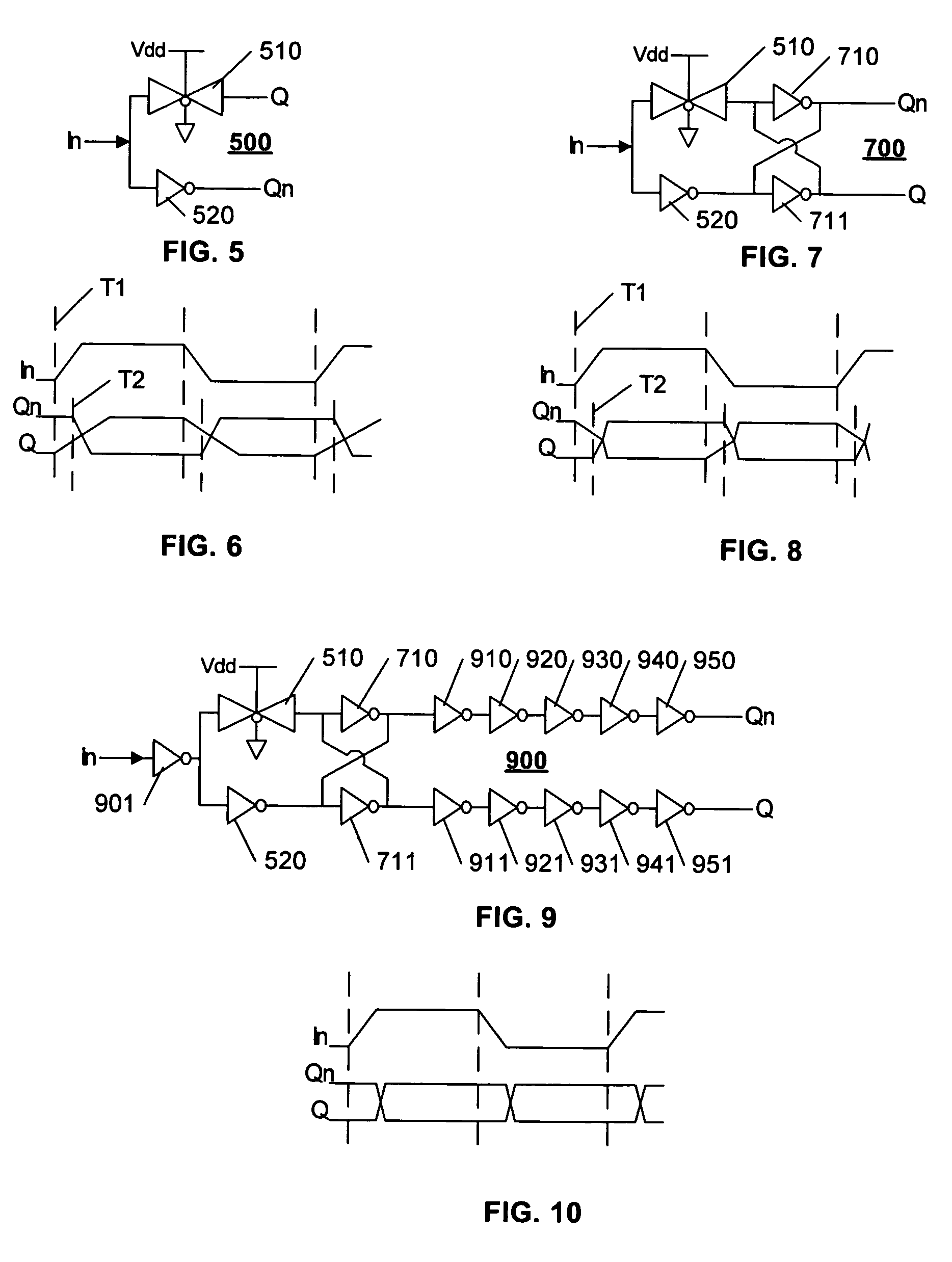
[0018]FIG. 5 illustrates an example single-ended to differential converter 500 in accordance with this invention. The converter 500 includes a transmission gate 510 that provides an in-phase output Q, and an inverter 520 that provides an out-of-phase signal Qn. The transmission gate 510 is illustrated as a complementary gate, with the active-high gating input tied to voltage source Vdd, and active-low gating input tied to ground. Thus, the transmission gate is always enabled to pass the input signal In to Q.

[0019]FIG. 6 illustrates an example timing-diagram of the converter of FIG. 5. Because the transmission gate 510 is always enabled, a transition of the input In at T1 initiates a virtually simultaneous transition of the output Q at T1. The inverter T2, on the other hand, is in a non-conducting state, and the output Qn exhibits a latency before the transition is initiated, at T2. As illustrated, although the transition of Q is initiated before the transition of Qn, the transition ...


PUM


Abstract

A single-ended to differential converter uses a cross-coupled latch that maximizes the output zero-crossing symmetry and is self compensating over PVT variations. An in-phase driving signal is provided by an always-on transmission gate coupled to the input. An out-of-phase driving signal is provided by an inverter coupled to the input. The in-phase and out-of-phase driving signals each drive an input of the cross-coupled latch. The in-phase driving signal from the always-on transmission gate starts to bring the cross-coupled latch into conduction, and when the out-of-phase driving signal arrives, the simultaneous driving of the cross-coupled latch causes a rapid and symmetric transition of both outputs of the cross-coupled latch.

Description

FIELD OF THE INVENTION[0001]This invention relates to the field of electronic circuits, and in particular, to a circuit that converts a single-ended signal into a pair of differential signals with low skew between the differential signals.BACKGROUND ART[0002]Differential signals are commonly used in electronic circuits and systems. In information-carrying signals, the use of differential signals provides the opportunity to apply noise-canceling techniques. In clocking signals, differential clocks are commonly used to provide high-speed switching capabilities.[0003]The use of differential signaling typically requires complementary symmetry between the pair of differential signals, including coincident switching. An offset of switching time between the pair of differential signals is termed “skew”, and low-skew circuits are preferred for optimal differential signal processing, particularly at high speeds.[0004]FIG. 1 illustrates a conventional circuit for converting a single-ended sig...

Claims


Application Information

Patent Timeline
Patent Type & Authority Patents(United States)
IPC IPC(8): H03K17/62
CPCG06F1/10
Inventor DAVIS, BRADLEY KENDALL
Owner TELEFON AB LM ERICSSON (PUBL)
Why Eureka
Try Eureka