Lithographic apparatus, device manufacturing method, and angular encoder

a technology of angular encoder and lithographic apparatus, which is applied in the field of lithographic projection apparatus, can solve the problems of too onerous requirements for lens dynamics

Active Publication Date: 2006-10-10
ASML NETHERLANDS BV
View PDF8 Cites 19 Cited by
  • Summary
  • Abstract
  • Description
  • Claims
  • Application Information

AI Technical Summary

Benefits of technology

[0009]By measuring the position of the projection system on a measurement axis passing through an invariant point, that is a point about which a rotation of the projection system does not cause a translation of the image, calculation of the necessary corrections is simplified and the number of sensors necessary can be reduced.
[0013]Preferably a sensor of the second measurement system, measuring the position of the projection system, that primarily measures a given degree of freedom, is mounted on the reference frame rigidly with a high stiffness, i.e. relative to the sensor of the first measuring system, measuring the position of the substrate table, that primarily measures the corresponding degree of freedom, the arrangement of sensors can be made more compact and the crosstalk between sensors minimized. Accordingly, the requirements on relative positional stability of the sensors in each system can be reduced.
[0020]This arrangement provides a single signal that is indicative of the relative rotation of the target and optical module, rather than two signals representing linear movements which must then be processed to give an indication of angle. Also, the sensitivity of the device is not limited by the arm that can be provided between two linear measurements, rather the opposite angle sensitivity of the two optical paths serves to amplify the signal.

Problems solved by technology

Otherwise, the requirements on the lens dynamics would be too onerous.

Method used


Image

  • Lithographic apparatus, device manufacturing method, and angular encoder
  • Lithographic apparatus, device manufacturing method, and angular encoder
  • Lithographic apparatus, device manufacturing method, and angular encoder

Examples


first embodiment

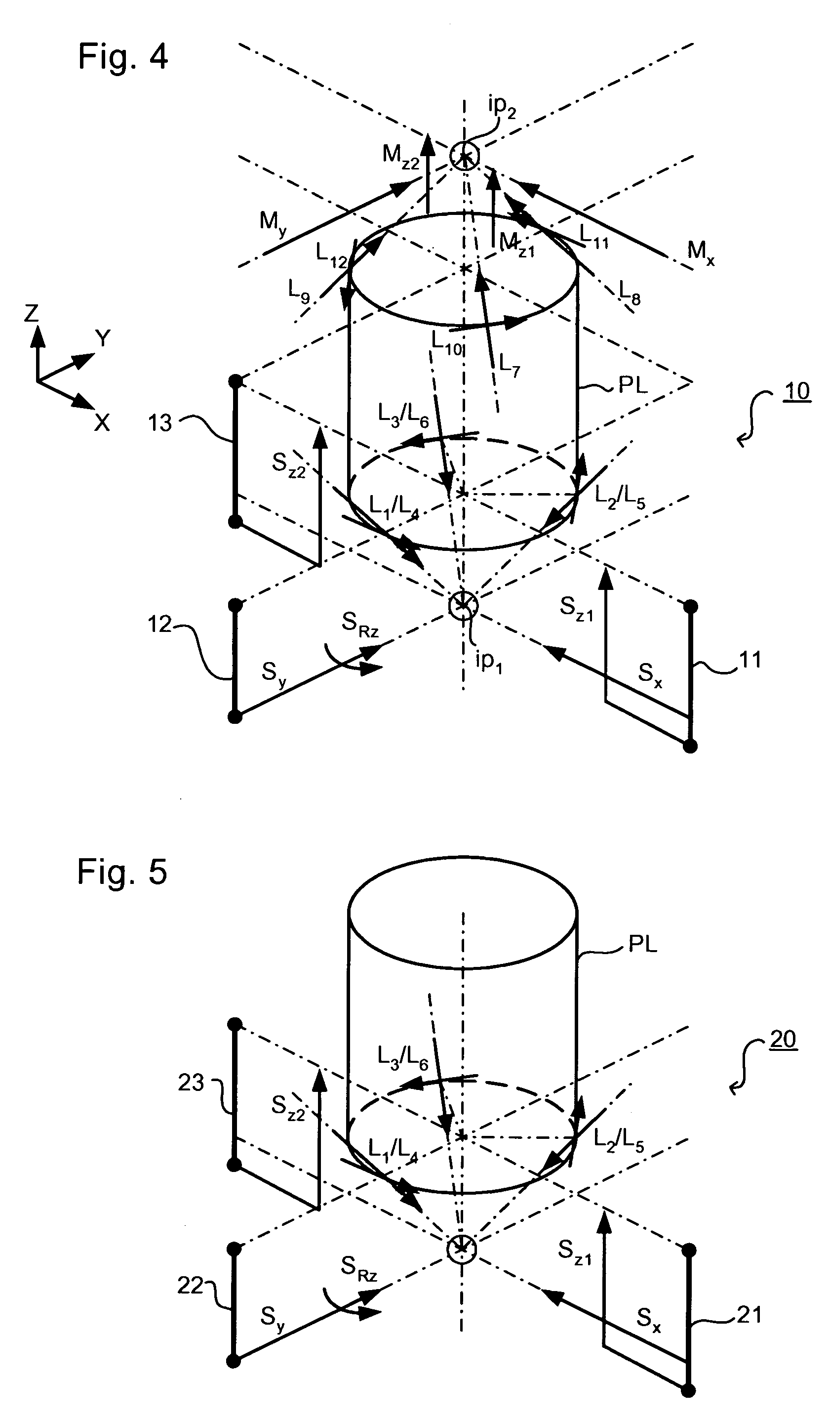
[0064]FIG. 5 shows the arrangement at the bottom of the projection system PL. This has an arrangement of sensors 20 mounted on sensor blocks 21, 22, 23 that is essentially the same as in the However, no sensors are mounted at the top of the projection system PL, instead the position of the mask table is measured using interferometers (not shown) mounted on the projection lens. This arrangement reduces the number of redundant sensors but the accuracy of the measurements is dependent on the relatively long path through the reference frame between mask level and substrate level. Thermal drift and dynamic movement of the reference frame must therefore be reduced further.

[0065]In a third embodiment of the present invention, which may be the same as the first embodiment of the invention save as described below, the sensors for measuring the position of the projection system are mounted rigidly and thermally stably in relation to corresponding substrate table position sensors.

[0066]As sho...

fifth embodiment

[0072]the present invention, which may be the same as the third save as described below, omits certain measurements and may be used where the corresponding movement so the projection system are expected to be small.

third embodiment

[0073]As shown in FIG. 8, the sensor arrangement 50 includes substrate table position sensors that are the same as the The position sensors for the projection system are mounted on sensor blocks 51, 52 to which corresponding substrate table sensors are mounted but only measure X, Y and Rz movements of the projection system using measurement axes L2, L1 and L3 respectively. No measurement of Rx, Ry and Z position of the projection system is made and this embodiment is therefore used only when movements in these directions can be assumed small enough.


PUM

PropertyMeasurementUnit
wavelengthaaaaaaaaaa

Abstract

In a lithographic projection apparatus, a measuring system configured to measure the position of the projection system relative to a reference frame includes sensors rigidly mounted in relation to counterpart sensors of a measuring system measuring the substrate table position. An angular encoder which sends light from a target down two optical paths having opposite sensitivities to tilt is used to measure rotation of the projection system about its optical axis.

Description

CROSS REFERENCE TO RELATED APPLICATION[0001]This application claims priority to European Application 03252746.7, filed Apr. 29, 2003, the entire contents of which are incorporated herein by reference.BACKGROUND OF THE INVENTION[0002]1. Field of Invention[0003]The present invention relates to lithographic projection apparatus and to device manufacturing methods. The present invention also relates to an angular encoder.[0004]2. Description of the Related Art[0005]A lithographic apparatus is a machine that applies a desired pattern onto a target portion of a substrate. Lithographic apparatus can be used, for example, in the manufacture of integrated circuits (ICs). In that circumstance, a patterning device, such as a mask, may be used to generate a circuit pattern corresponding to an individual layer of the IC, and this pattern can be imaged onto a target portion (e.g. including part of one, or several, dies) on a substrate (e.g. a silicon wafer) that has a layer of radiation-sensitive...

Claims


Application Information

Patent Timeline
Patent Type & Authority Patents(United States)
IPC IPC(8): G01C3/08G01B11/14G03B27/54G03F7/20H01L21/027
CPCG03F7/70258G03F7/7085A23P30/00A23P30/10A23L7/196
Inventor LEENDERS, MARTINUS HENDRIKUS ANTONIUSMEIJER, HENDRICUS JOHANNES MARIAVAN DER PASCH, ENGELBERTUS ANTONIUS FRANSISCUSRENKENS, MICHAEL JOZEF MATHIJSRUIJL, THEO ANJES MARIA
Owner ASML NETHERLANDS BV
Why Eureka
Try Eureka