Method and apparatus for waste vitrification

Active Publication Date: 2006-10-10
STIR MELTER
View PDF35 Cites 38 Cited by
  • Summary
  • Abstract
  • Description
  • Claims
  • Application Information

AI Technical Summary

Benefits of technology

[0019]It is an object of the present invention to provide a high throughput hazardous waste vitrifying method and apparatus which quickly melts vitrifiable batch materials.
[0020]Another object of the present invention is to provide a

Problems solved by technology

Disposal of hazardous waste is a pressing environmental problem.
Hazardous waste such as radioactive materials from nuclear reactors have long term radioactivity which makes conventional methods of solid waste disposal inappropriate.
There is significant danger of such materials leaching from a solid waste disposal facility and entering the water supply.
Problems associated with vitrification processes developed previously include low throughput resulting in a high disposal cost per unit of hazardous waste material.
A primary problem with the resultant static glass furnace was that its output was limited to a rate of 4 pounds of vitrified waste per hour per square foot of furnace su

Method used


Image

  • Method and apparatus for waste vitrification
  • Method and apparatus for waste vitrification
  • Method and apparatus for waste vitrification

Examples


Example

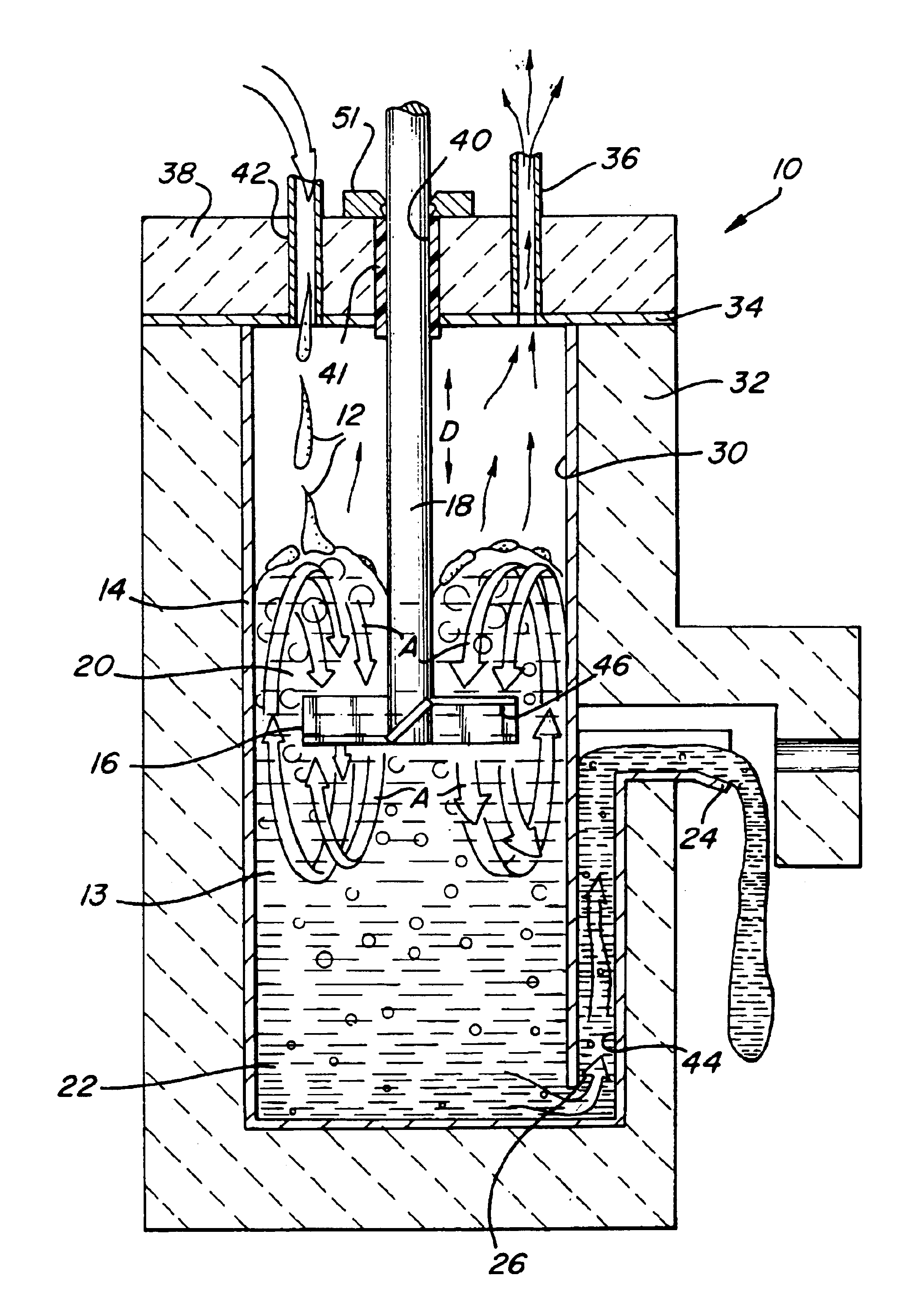
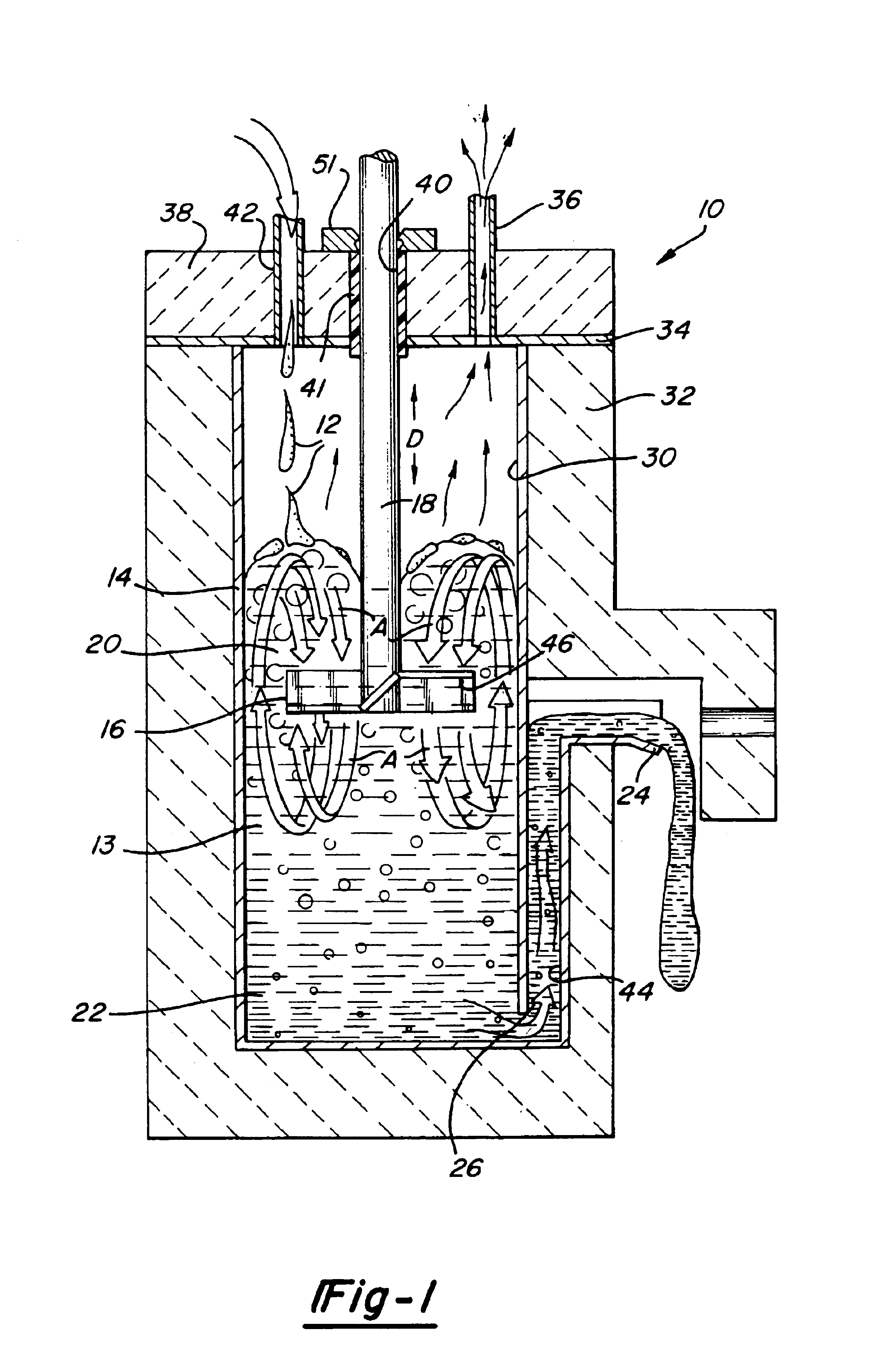
[0027]Referring now to FIG. 1, the waste vitrification apparatus 10 of the present invention is shown receiving a feed stream 12 preferably comprising an aqueous slurry of glass batch and waste materials. The feed stream 12 could also be dry glass batch or melted glass batch and waste materials fed into the apparatus 10. The glass batch is preferably boro-silicate batch selected for its low melting point in the range of 950° C. to 1050° C. Other compositions may be used depending upon the thermal and chemical limitations of the vessel. As used herein, the term glass batch is intended to encompass both raw materials for making glass and fused and partially fused materials used in making glass known as frit or cullet. The wastes to be disposed of are either radioactive wastes, hazardous chemical wastes, or other wastes which require a durable disposal medium.

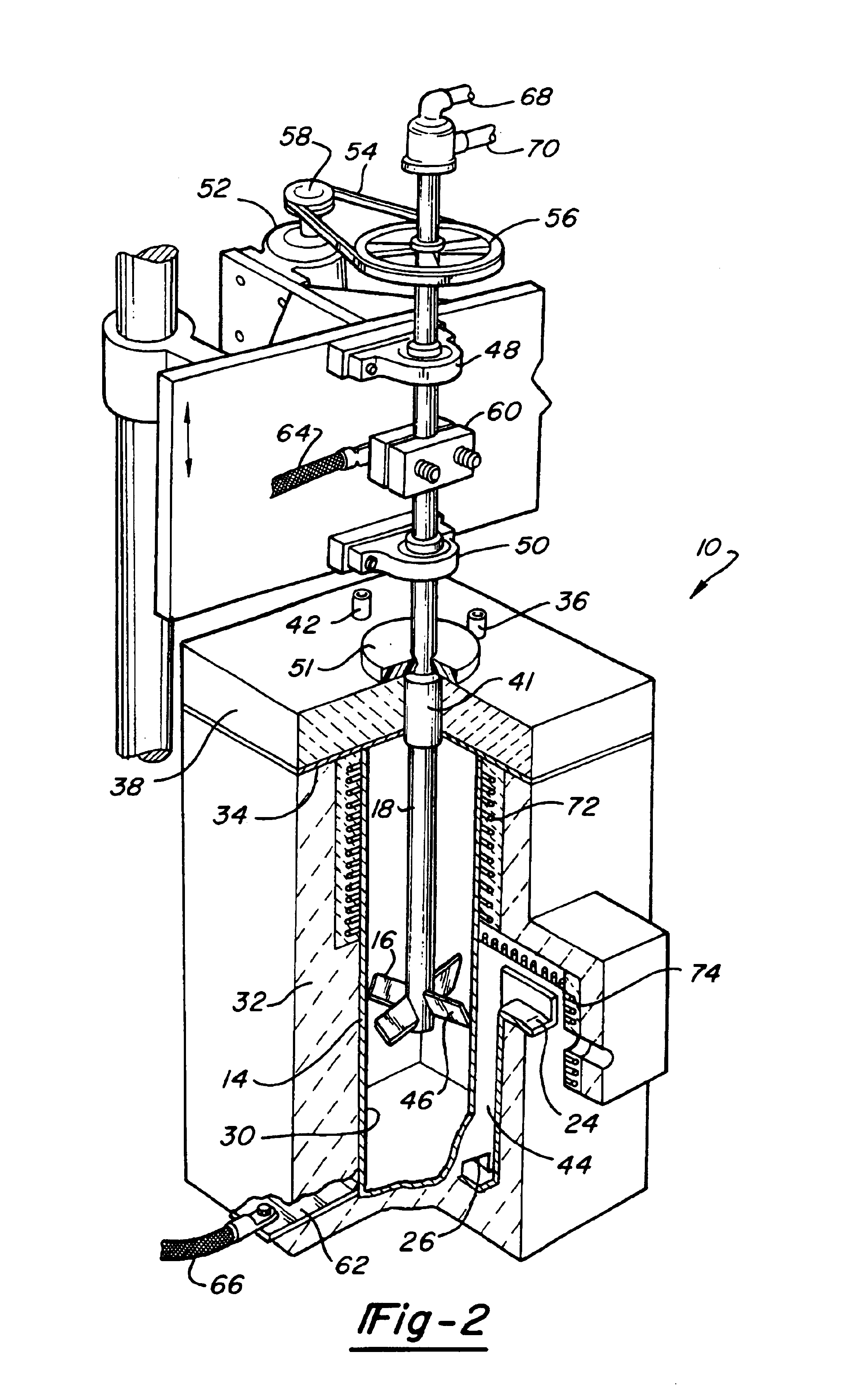
[0028]A vessel 14 is provided to receive the feed stream 12 in a glass melt 13. A mixing impeller 16 is disposed in the vessel 1...


PUM

PropertyMeasurementUnit
Electrical conductivityaaaaaaaaaa
Massaaaaaaaaaa
Depthaaaaaaaaaa

Abstract

A waste vitrification apparatus (10) having rotatable mixer impeller (16) functioning as a shaft electrode (60) and metallic vessel (14) functioning as a vessel electrode (62). A stream (12) of waste material and vitrifiable material are mixed and melted in the vessel (14) for vitrification. The waste vitrification method converts a feed stream (12) by mixing the feed stream into a glass melt (13) and melting glass batch of the feed stream (12) to form a foamy mass. The stream is dispersed by the impeller (16) to form a foam which is then densified in a settling zone (22), recovered through a spout (24) and solidified in storage containers. Means are provided to adjust the location of the mixing impeller (16) in the vessel (14) to change the depth of the settling zone (22). The impeller (16) is mounted on a drive shaft (18) having a recirculating coolant flow.

Description

[0001]This is a divisional of co-pending application Ser. No. 07 / 510,556 filed on Apr. 18, 1990.TECHNICAL FIELD[0002]The present invention relates to a method and apparatus for vitrifying wastes. More particularly, the resent invention relates to a glass melting furnace having an impeller to mix and foam vitrifiable materials and waste materials which are fed to the melter, melted and recovered to form a solid vitrified mass.BACKGROUND ART[0003]Disposal of hazardous waste is a pressing environmental problem. Hazardous waste such as radioactive materials from nuclear reactors have long term radioactivity which makes conventional methods of solid waste disposal inappropriate. There is significant danger of such materials leaching from a solid waste disposal facility and entering the water supply.[0004]Vitrification of hazardous solid wastes has been proposed and implemented on a relatively small scale. Problems associated with vitrification processes developed previously include low t...

Claims


Application Information

Patent Timeline
IPC IPC(8): C03B5/027C03B5/00C03B5/033C03B5/187G21F9/30
CPCC03B5/005C03B5/027C03B5/033C03B5/1875C03B5/26G21F9/305Y10S422/903Y02P40/50Y02P40/57
Inventor RICHARDS, RAY S.
Owner STIR MELTER
Why Eureka
Try Eureka