Hand-held power tool

a power tool and hand-held technology, applied in the field of hand-held power tools, can solve the problems of reducing the output of the tool, early fatigue of the user, and expensive constructional measures, and achieves the effects of ensuring the operation ability, increasing the performance capability of the component, and cost-effective production

Active Publication Date: 2006-10-17
HILTI AG
View PDF10 Cites 21 Cited by
  • Summary
  • Abstract
  • Description
  • Claims
  • Application Information

AI Technical Summary

Benefits of technology

[0008]The spring stiffens the connection rod and insures its operational ability during operation of the power tool. Only the peak pressures are stored by the spring and only a small portion of the peak pressure is transmitted further. As a result, the occurring peak pressures are not transmitted to the surrounding components and are substantially reduced, which increases the performance capability of this components and permits to eliminate the extensive constructional measures undertaken previously for securing these components. Consequently, the entire hand-held tool can be produced cost-effectively. In addition, the tool operator exhibits fatigue symptoms much later than an operator of a conventional power tool during a prolong use of the power tool, which improves the work efficiency.
[0009]Advantageously, the piston is formed as a driving piston which is pneumatically connected with percussion piston of the percussion mechanism. These percussion mechanisms are known in the art as pneumatic percussion mechanisms that are particularly used in hammer drills and / or chisel hammers. The inventive connection rod damps the return pulses and vibrations of the driving piston.
[0014]According to an alternative embodiment of the present invention the spring is formed as an air spring. The air spring is formed by a closed air chamber. For mounting of the connection rod, there is provided an aeration opening which is closed after the two parts of the connection rod are connected with each other. Under action of a load, the two parts are displaced relative to each other, with the air in the air chamber being compressed. Subsequently, the compressed air expands, displacing the two parts away from each other, with the connection rod assuming its initial length. Under a tension load applied to the two parts, a suction effect is produced that prevents the two parts from sliding from each other, without the mounting opening being open. This prevents the two parts from being lost. As a result of the telescopic arrangement of the two parts of the connection rod, a maximum displacement path is predetermined and is limited upon the failure of the air spring, e.g., as a result of leakage through the sealing.

Problems solved by technology

This leads, in particular with an extended operation of the power tool, to an early fatigue of the user and to a reduction of the tool output.
The drawback of the known solution consists in that in order to insure a sufficient damping of the generated impact pulses and vibrations, expensive constructional measures are required.

Method used


Image

  • Hand-held power tool
  • Hand-held power tool
  • Hand-held power tool

Examples


Embodiment Construction

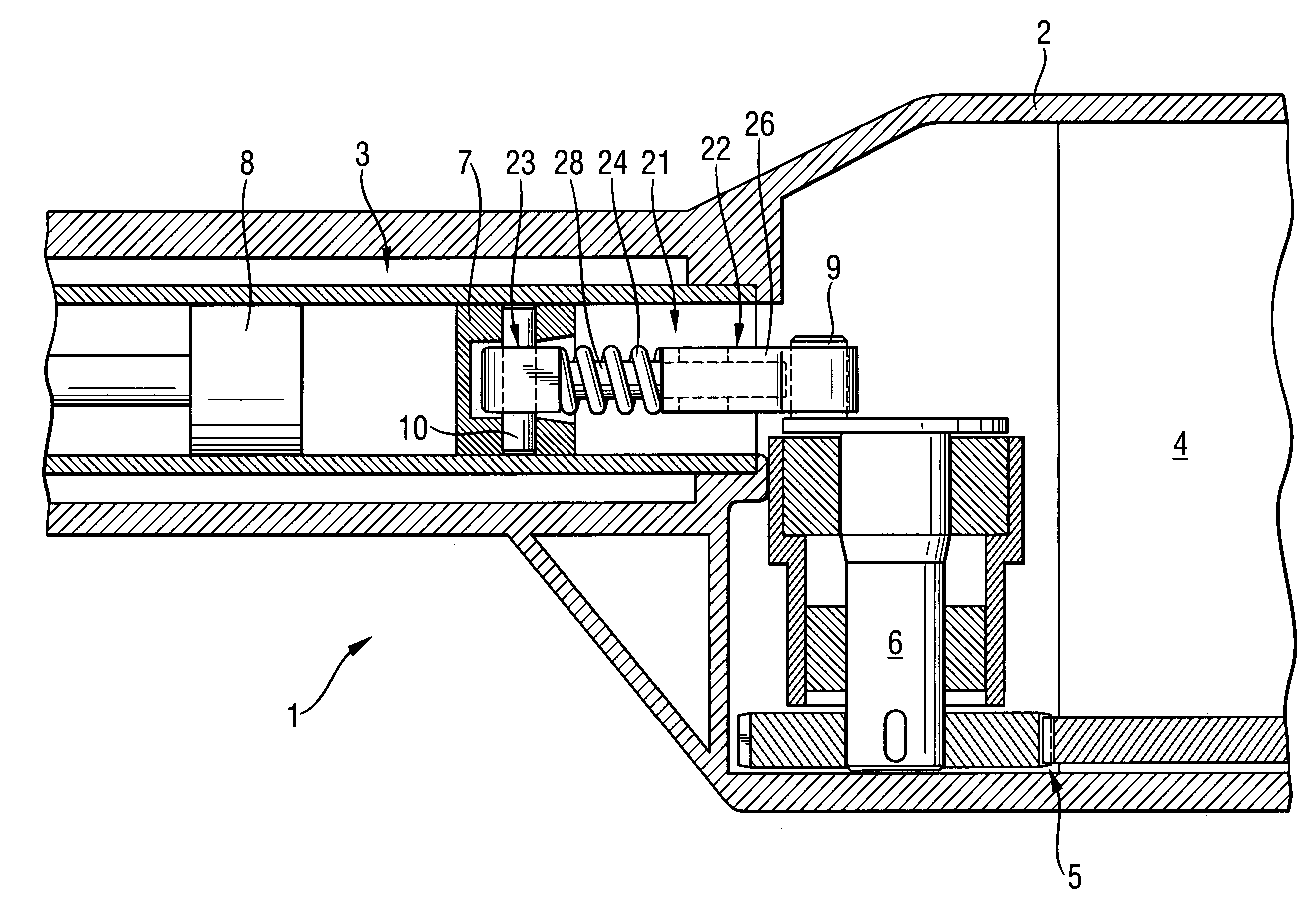
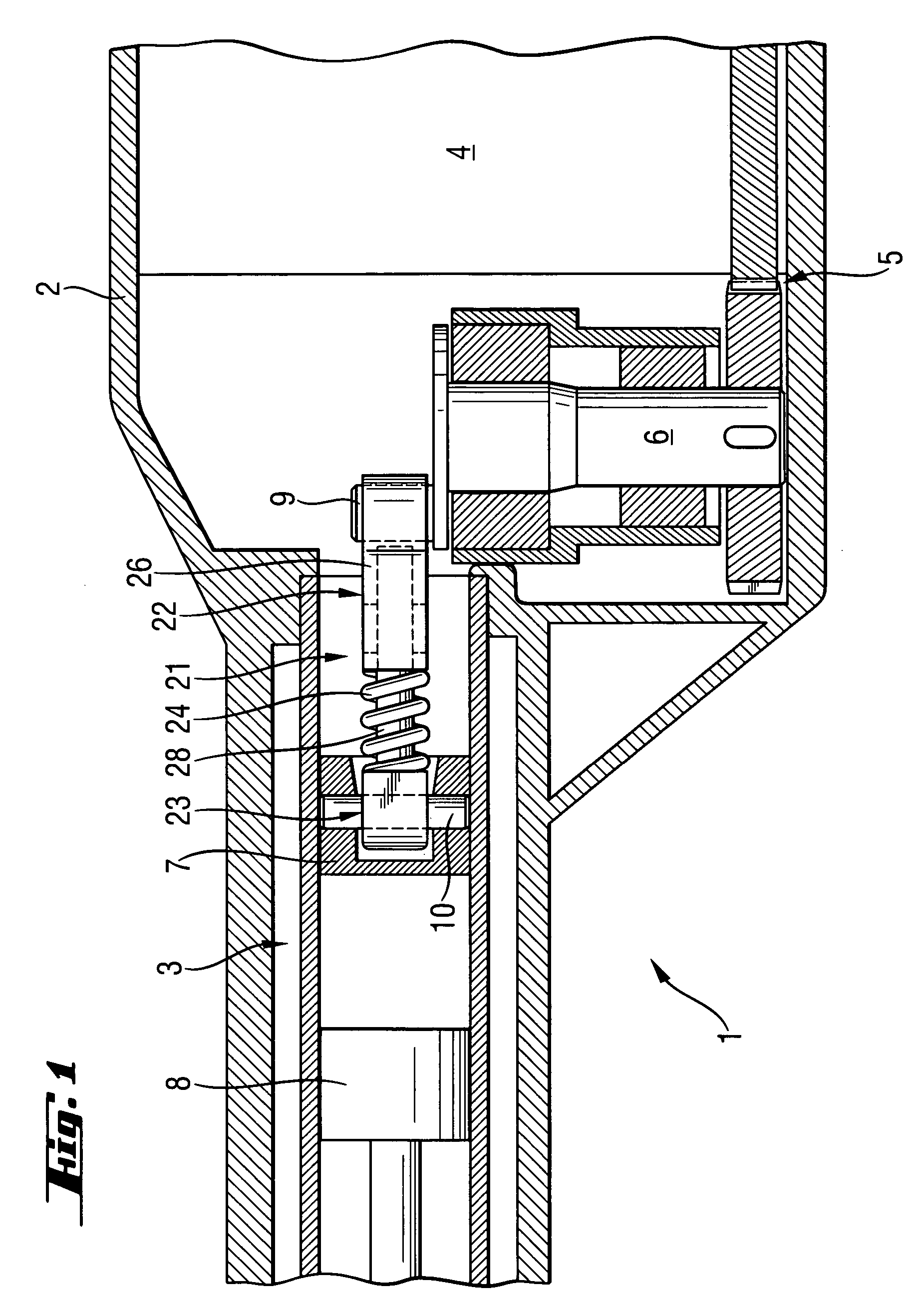
[0023]A hand-held power tool / according to the present invention, which is shown in FIG. 1, includes a housing 2, a percussion mechanism 3 located in the housing 2, a motor 4, and a gear unit 5 that drivingly connects the motor 4 with the percussion mechanism 3. The percussion mechanism 3 has an eccentric 6 and a driving piston 7 which is connected with the eccentric 6 by a connecting rod 21. The driving piston 7 pneumatically cooperate with a percussion piston 8 that also forms part of the percussion mechanism.

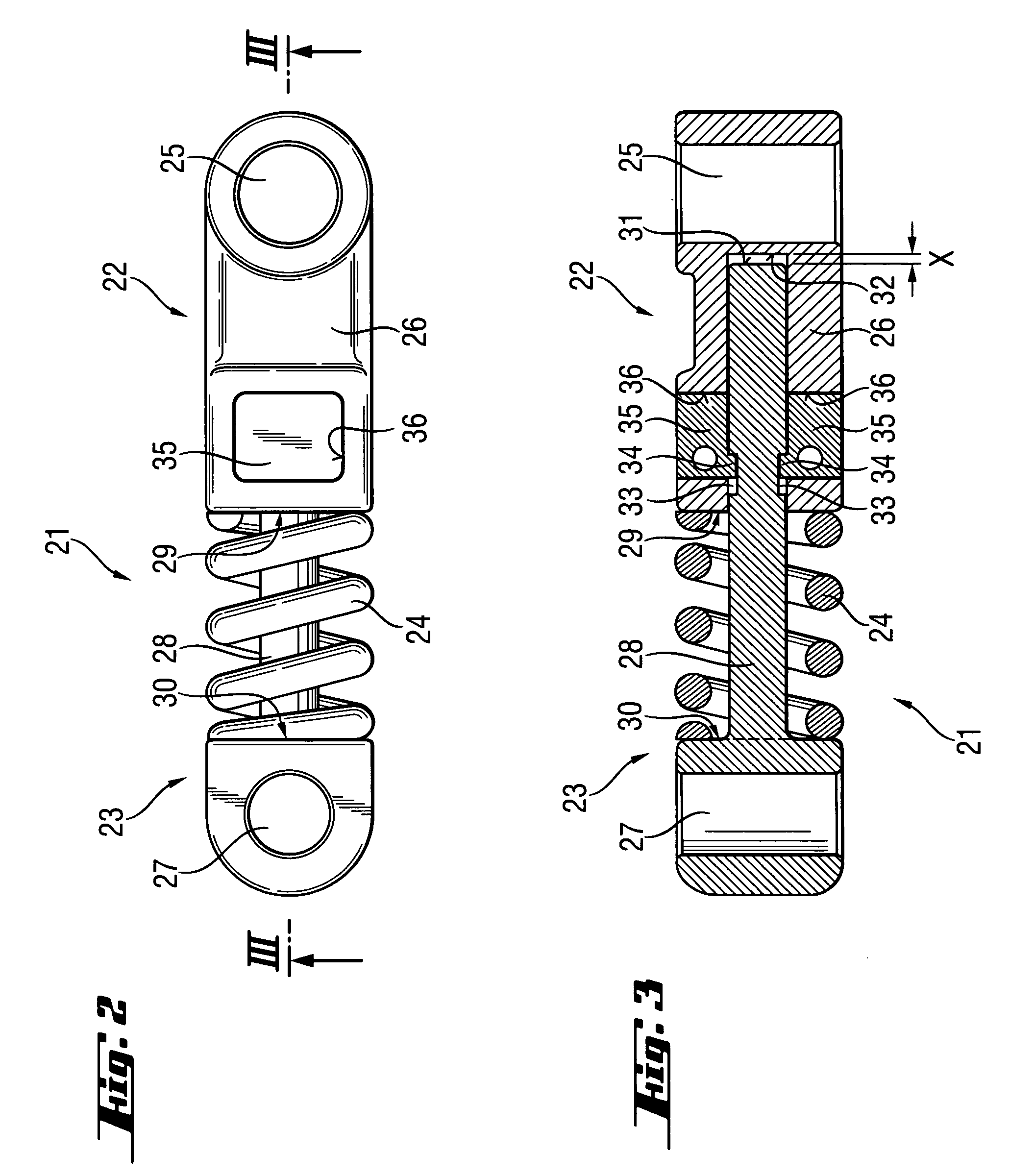
[0024]The connecting rod 21 has a first part 22 which is connected with the eccentric 6, and a second part 23 which is connected with the driving piston 7. A helical spring 24 is arranged between the first part 22 and the second part 23. The first part 22 has a receiving opening for receiving a journal 9 provided on the eccentric 6 and a sleeve section 26. The second part 23 has an opening 27 for receiving a connection bolt 10 that connects the second part 23 with the driving ...


PUM

PropertyMeasurementUnit
pressuresaaaaaaaaaa
dampingaaaaaaaaaa
peak pressuresaaaaaaaaaa

Abstract

A hand-held power tool includes a percussion mechanism (3) arranged in the tool housing (2), and a motor (4) for driving the percussion mechanism and connected therewith by a gear unit (5), with the percussion mechanism including an eccentric (6) a piston (7), and a connection rod (21; 41) connecting the eccentric with the driving piston (7) and having a first part (22; 42) connectable with the eccentric (6), a second part (23; 43) connectable with the drive piston (7) and telescopically displaceable relative to the first part (22; 42), and a spring for damping vibrations occurring during operation of the power tool and arranged between the first (22; 42) and second (23; 43) parts.

Description

BACKGROUND OF THE INVENTION[0001]1. Field of the Invention[0002]The present invention relates to a hand-held power tool, in particular, to a motor-driven drilling and / or chiselling tool including a housing, a percussion mechanism arranged in the housing, and a motor drivingly connectable with the percussion mechanism by a gear unit, with the percussion mechanism having an eccentric, a piston, and a connection rod for connecting the eccentric with the piston. The present invention also relates to a percussion mechanism for use in the power tool and to a connection rod that connects the eccentric with the driving piston.[0003]2. Description of the Prior Art[0004]In the conventional tools of the type described above, occurring peak pressures, e.g., impact pulses, are dampingly transmitted by the connection rod, e.g., by the eccentric to the surrounding components. As a result, the generated impact pulses and vibrations are sensed by a tool user holding the power tool handle. This leads...

Claims


Application Information

Patent Timeline
Patent Type & Authority Patents(United States)
IPC IPC(8): B23B45/16B25D9/00B25D9/10B25D11/06B25D11/08B25D11/10B25D11/12B25D16/00B25D17/00B25D17/24
CPCB25D11/125B25D17/00B25D17/24B25D17/06B25D2217/0023
Inventor FUNFER, JOSEF
Owner HILTI AG
Why Eureka
Try Eureka