Vehicle cargo bed extender having a pin lock assembly

a technology of cargo bed and extender, which is applied in the direction of transportation and packaging, transportation items, and items transportation vehicles, etc., can solve the problems of affecting the proper deployment of a conventional bed extender, the use of conventional truck bed extenders is highly problematic, and the effective cargo area of the vehicle is increased. , the effect of convenient us

Active Publication Date: 2006-10-17
GOLDMAN SACHS CREDIT PARTNERS L P +1
View PDF15 Cites 43 Cited by
  • Summary
  • Abstract
  • Description
  • Claims
  • Application Information

AI Technical Summary

Benefits of technology

[0019]At least one lock assembly having a main body is disposed upon one of the sidewalls of the bed extender. The lock assembly includes a locking pin that is operable to be selectively extended and retracted from one end of the main body to engage with and disengage from the vehicle sidewall. The lock assembly further includes a handle disposed at the end of the main body opposite the locking pin and a lever arm disposed therebetween. The handle and lever arm are operative to move between a first and a second position thereby cooperating to facilitate the extension and retraction of the locking pin from the main body such that the extension of the locking pin locks the bed extender to the vehicle sidewall in the stowed and deployed positions to prevent any uncommanded movement of the extender. The locking assembly is further operative to hold the locking pin in the extended and retracted positions respectively until selectively moved between positions.
[0020]Thus, the vehicle cargo bed extender of the present invention overcomes the drawbacks and disadvantages of the prior art by providing an increase in the effective cargo area of the vehicle while, at the same time, providing a pivoting means for rapid changeover from one mode of vehicle operation to another. The present invention also provides an improved locking and retaining mechanism to lock the bed extender in both the deployed and stowed positions to prevent uncommanded movement. The locking mechanism of the present invention is simple, cost effective, easy to use, and remains in the extended and retracted position until selectively moved.

Problems solved by technology

While such bed extenders known in the related art have generally worked for their intended purposes, disadvantages still remain regarding their use for certain vehicle applications.
However, the shorted rear bed 26 of the crossover vehicle 40 makes the use of conventional truck bed extenders highly problematic.
This is due to the fact that a crossover vehicle 40 most often employs some type of bed accessory, such as a tool box 34 or tonneau cover 36 discussed above, which interferes with the proper deployment of a conventional bed extender.
While a pivoting bed extender provides improvements that overcome the drawbacks of conventional extenders, their use presents another problem.
However, they are generally complex in their design, construction, and use.
The complex structure of the plunger locking devices further causes them to be prone to jamming and corrosion in the environment to which the bed extender is exposed.
This makes it very difficult for a single individual to operate these locking mechanisms so that the bed extender can be moved from one position to the other.
Furthermore, if a conventional locking device is adapted so that it may be actuated and temporarily latched into an unlocked position to overcome this limitation, the adaptation adds further complexity and cost to the device.
Simply stated, the conventional approaches to locking and retaining devices as employed in conventional type bed extenders are complex, expensive, and difficult to use.
Moreover, an attempt to employ conventional locking and retaining devices with the pivotal style bed extenders often fail to provide the desired result of a simplified, quickly changeable bed extender designed with the current consumer demands in mind.

Method used


Image

  • Vehicle cargo bed extender having a pin lock assembly
  • Vehicle cargo bed extender having a pin lock assembly
  • Vehicle cargo bed extender having a pin lock assembly

Examples


Embodiment Construction

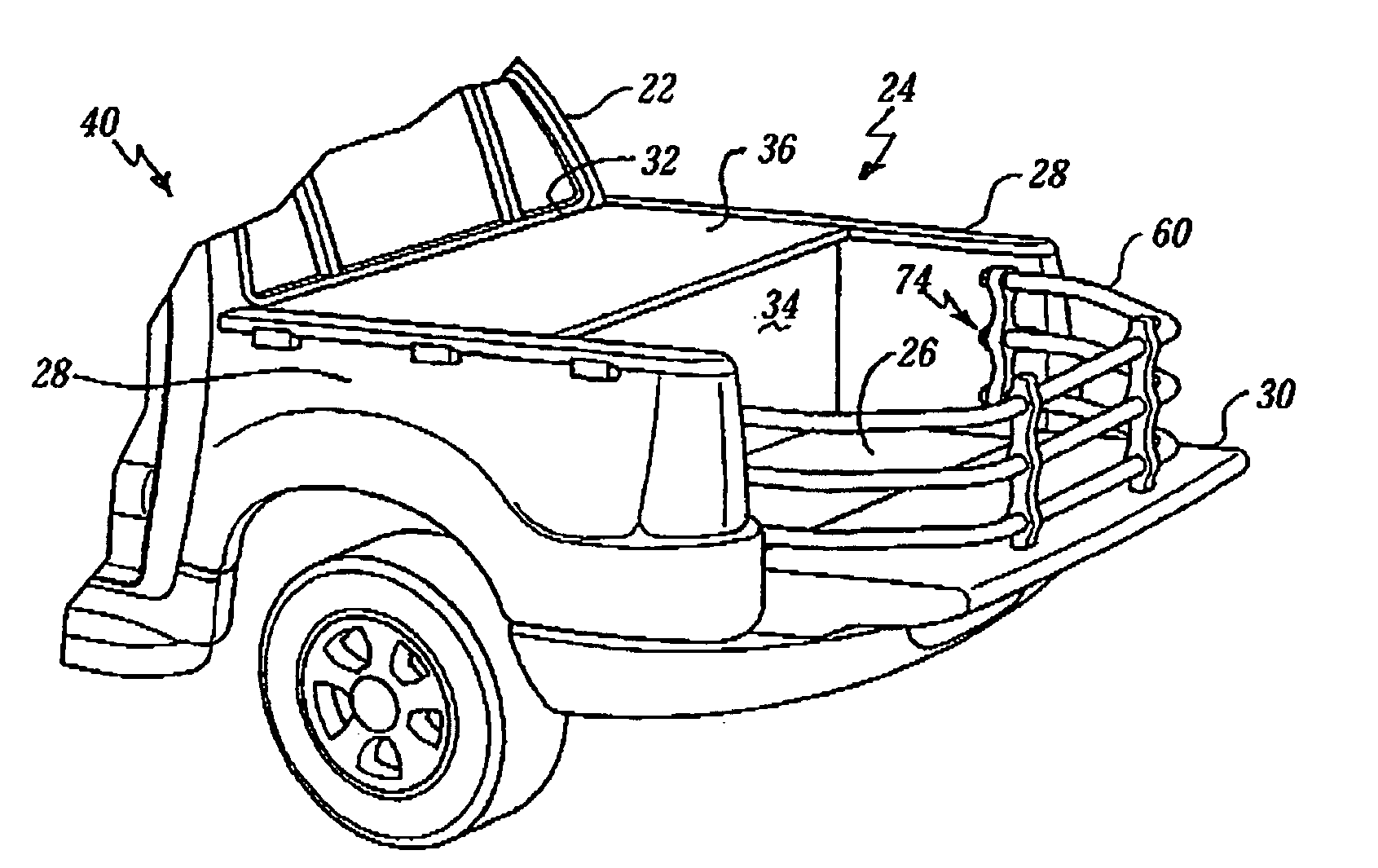
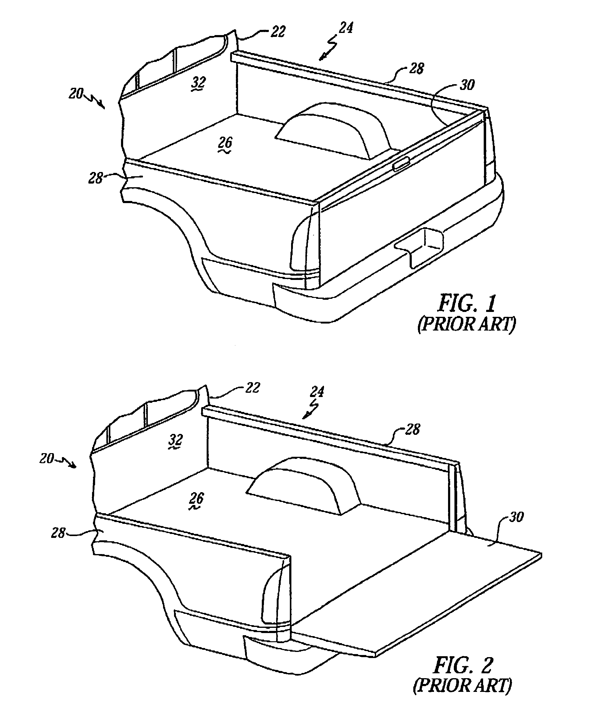
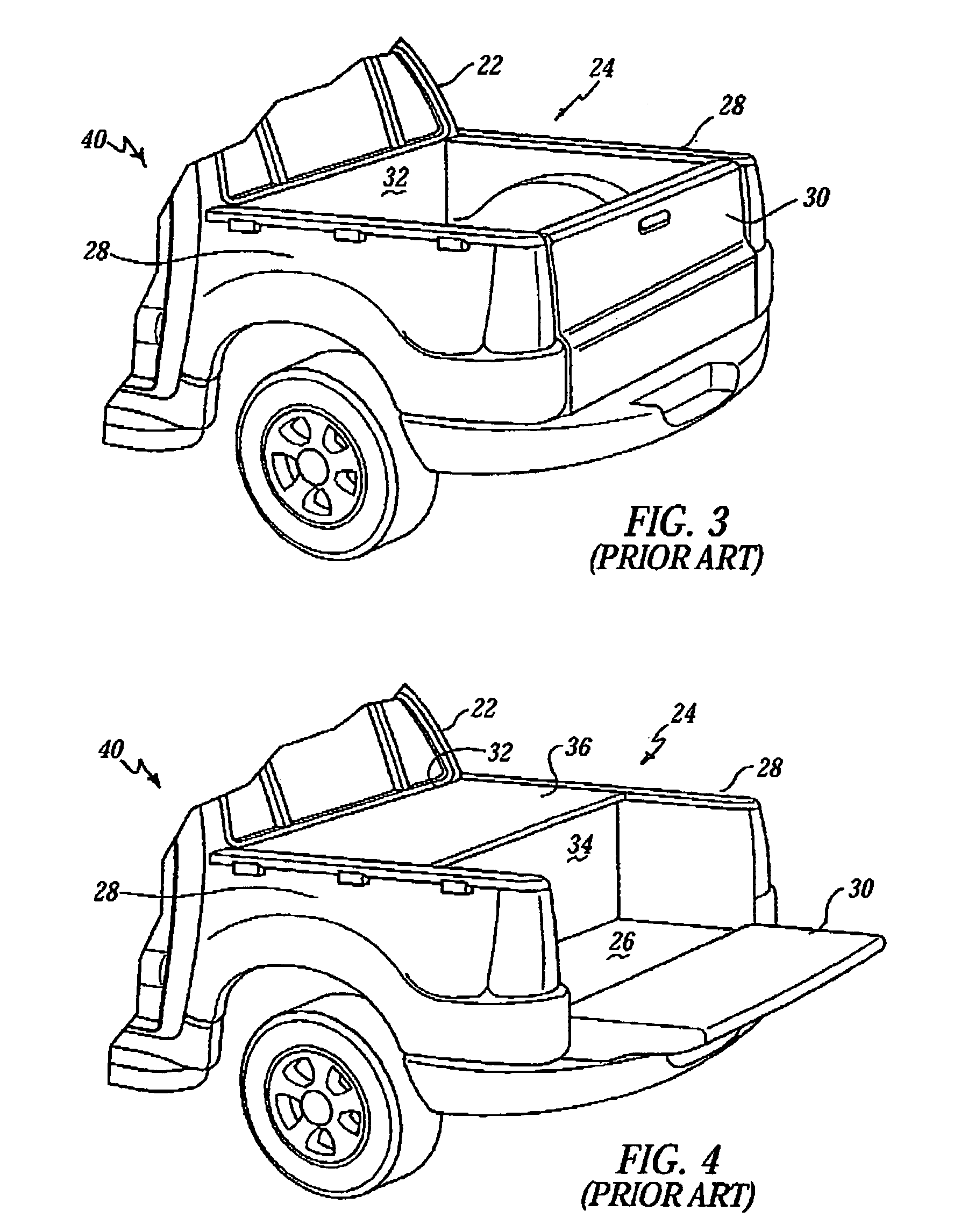
[0037]With the foregoing description of the related art in mind, the present invention is a vehicle cargo bed extender, generally indicated at 60 in FIGS. 5–10, where like numerals are used to designate like structure throughout the drawings. The vehicle cargo bed extender 60 is adapted to be employed in conjunction with a SUV / Pick-up cross-over style vehicle 40 as generally illustrated in FIGS. 3–6. However, those having ordinary skill in the art should appreciate that the present invention may also be employed in a standard pick-up truck style vehicle 20 as illustrated in FIGS. 1 and 2. As noted above, similar to standard pick-up truck designs, SUV / Pick-up cross-over vehicles 40 typically have a cargo area 24 defined by a bed 26 and a pair of upstanding sidewalls 28 spaced from one another on either side of the vehicle bed 26. In addition, the cargo area 24 is defined by a rear wall 30 extending between the upstanding sidewalls 28 at one end of the vehicle bed 26. The rear wall 30...


PUM


Abstract

A vehicle cargo bed extender for a vehicle of the present invention includes a pair of sidewalls spaced from one another and a center wall extending therebetween. At least one lock assembly is disposed upon one of the sidewalls of the bed extender and includes a locking pin that operable to be selectively extended and retracted to engage with and disengage from the vehicle sidewall respectively. The lock assembly further includes a handle and a lever arm, which cooperate to facilitate the extension and retraction of the locking pin such that said extension of the locking pin locks the bed extender to the vehicle sidewall in the stowed and deployed positions to prevent any uncommanded movement of the extender. The locking assembly further operative to hold the locking pin in the extended and retracted positions respectively until selectively moved between positions.

Description

BACKGROUND OF THE INVENTION[0001]1. Field of the Invention[0002]The present invention relates, generally, to a vehicle cargo bed extender, and more specifically, to a bed extender that is adapted to pivot between a deployed position over a down tailgate and a stowed position forward of the tailgate and having a pin lock assembly adapted to selectively lock the bed extender in either the deployed or the stowed position.[0003]2. Description of the Related Art[0004]Pickup trucks are well known vehicles having rear cargo areas that are employed for utilitarian purposes. A representative example of this type of vehicle is generally indicated at 20 in FIG. 1. As is well known in the art, pickup trucks typically include a cab 22 in which the vehicle operator sits and a cargo area, generally indicated at 24. The cargo area 24 is typically disposed adjacent and to the rear of the cab 22. The cargo area 24 is typically defined by a bed 26 and pair of upstanding sidewalls 28 spaced from one an...

Claims


Application Information

Patent Timeline
Patent Type & Authority Patents(United States)
IPC IPC(8): B62D33/08B62C1/06
CPCB60P3/40
Inventor REED, TROY R.
Owner GOLDMAN SACHS CREDIT PARTNERS L P
Why Eureka
Try Eureka