Electric parking brake apparatus

a technology of electric brakes and brakes, which is applied in the direction of brake systems, brake components, transportation and packaging, etc., can solve the problems of large units, complex configuration, and control units, and achieve the effect of simplifying configuration

Inactive Publication Date: 2006-10-17
ADVICS CO LTD
View PDF19 Cites 27 Cited by
  • Summary
  • Abstract
  • Description
  • Claims
  • Application Information

AI Technical Summary

Benefits of technology

[0021]In contrast, in the case where the electric parking brake control unit is configured to detect generation of a predetermined failure in the electric parking brake apparatus and identify the details of the failure, and is connected to the second control unit so as to output to the second control unit a signal corresponding to the details of the failure, diagnosis of a failure relating to the electric parking brake apparatus can be executed, while a diagnosis signal output port provided in the second control unit is utilized. As a result, the electric parking brake control unit is not required to include the above-described storage device, dedicated diagnosis signal output port, etc. Accordingly, the electric parking brake control unit can be further reduced in size and further simplified in configuration.

Problems solved by technology

However, since the electric parking brake control unit of the above-described conventional apparatus includes various input circuits for receiving signals from various sensors and a complicated determination function for determining whether the automatic activation start condition is satisfied, which circuits and function are necessary for accomplishing the above-described automatic control function, the control unit has problems in that the unit is large and of complex configuration.
In other words, in the case where, among vehicles which carry an electric parking brake apparatus, some vehicles require the automatic control function and the remaining vehicles do not require the automatic control function, there has been a problem in that two types of electric parking brake control units must be prepared; i.e., an electric parking brake control unit having both a manual control function and an automatic control function as described above, and an electric parking brake control unit having only a manual control function and not having an automatic control function.

Method used


Image

  • Electric parking brake apparatus
  • Electric parking brake apparatus
  • Electric parking brake apparatus

Examples


Embodiment Construction

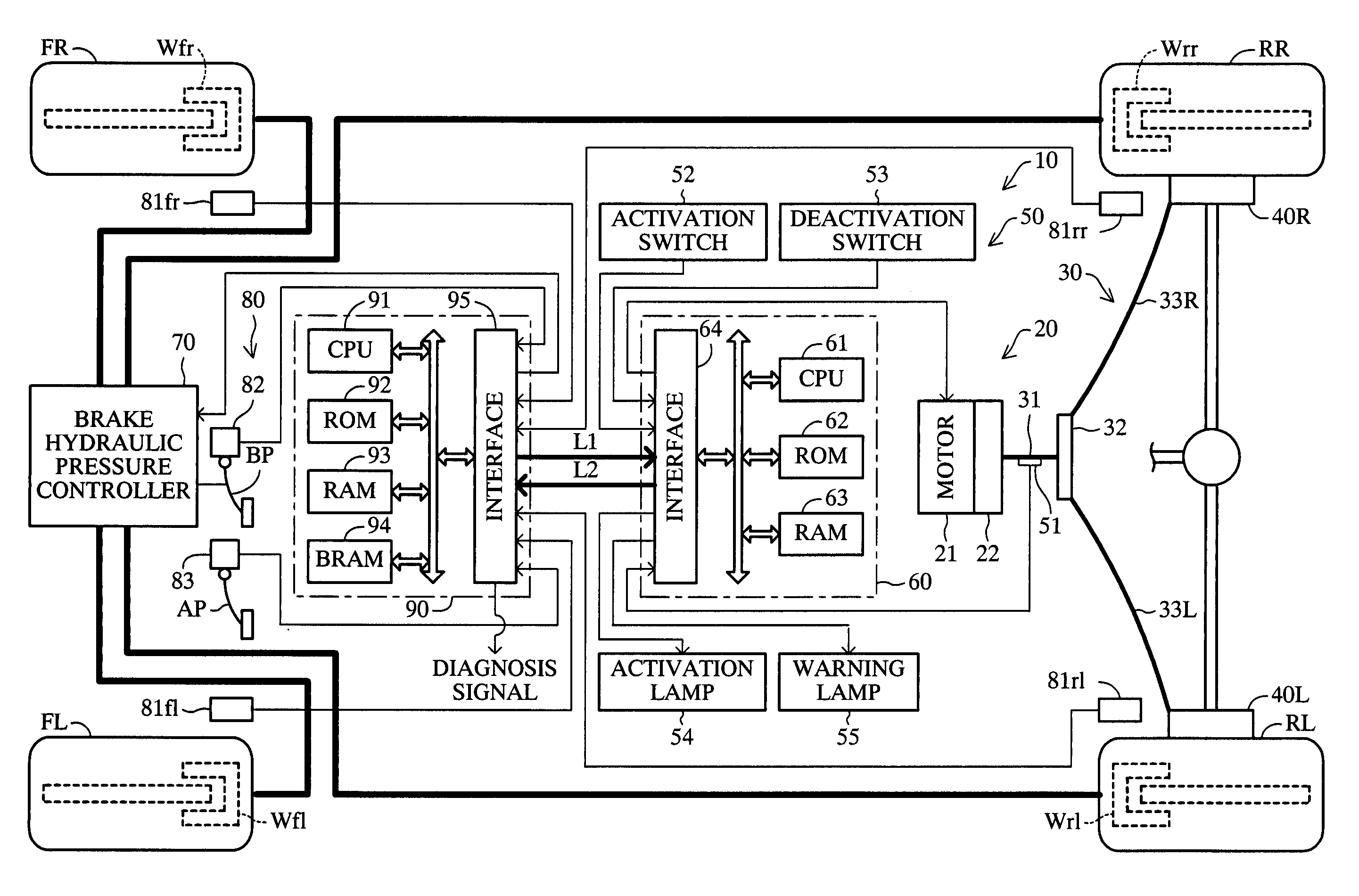
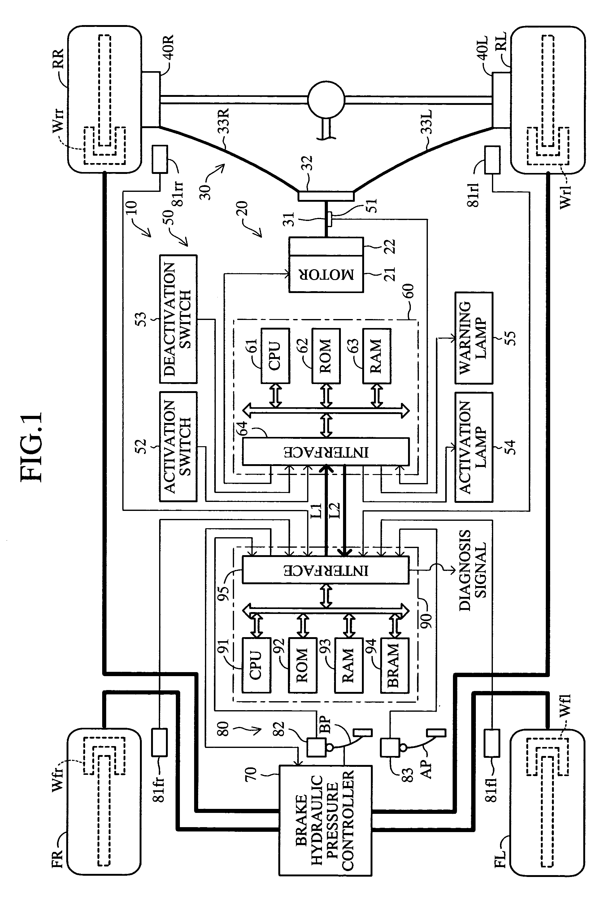
[0032]An embodiment of the present invention will now be described with reference to the drawings. FIG. 1 schematically shows the configuration of a vehicle on which is mounted an electric parking brake apparatus 10 according to the embodiment of the present invention. The vehicle is a four-wheel vehicle which has two front wheels (a front left wheel FL and a front right wheel FR) and two rear wheels (a rear left wheel RL and a rear right wheel RR) and which requires both the above-described automatic control function and the above-described manual control function.

[0033]The electric parking brake apparatus 10 includes a drive actuator section 20, a wire structure section 30, left-hand and right-hand parking brakes 40L and 40R provided adjacent to the two rear wheels, respectively, a sensor-switch-lamp system 50, and an electric parking brake control unit 60.

[0034]The drive actuator section 20 includes an electric motor 21 and a speed reduction mechanism 22. The electric motor 21 se...


PUM


Abstract

An electric parking brake control unit of an electric parking brake apparatus has an input section for receiving signals for performing automatic activation and deactivation, but does not have a determination function and a circuit for inputting signals from various sensors, which are necessary to determine whether to start the automatic activation/deactivation control. Therefore, when used in a vehicle which does not require an automatic control function and requires only a manual control function, the electric parking brake control unit can be used solely, with no signal line connected to the input section. When used in a vehicle which requires both the automatic control function and the manual control function, the input section is connected to a second control unit that can output signals for performing automatic activation and deactivation, whereby the electric parking brake control unit operates in cooperation with the second control unit.

Description

BACKGROUND OF THE INVENTION[0001]1. Field of the Invention[0002]The present invention relates to an electric parking brake apparatus capable of activating and deactivating a parking brake of a vehicle by use of electric drive means such as an electric motor.[0003]2. Description of Related Art[0004]Japanese Patent Application Laid-Open (kokai) No. 2001-322537 discloses a conventional electric parking brake apparatus of such a type. The disclosed apparatus includes an electric parking brake control unit, which receives a parking brake activation-deactivation signal generated upon operation of a manual switch and which drives an electric motor on the basis of the signal to thereby activate and deactivate a parking brake.[0005]Further, the electric parking brake control unit is connected to various sensors mounted on the vehicle, and is configured to determine, on the basis of signals from the sensors, whether a condition for starting automatic activation of the parking brake or a condi...

Claims


Application Information

Patent Timeline
Patent Type & Authority Patents(United States)
IPC IPC(8): B60T13/66B60T7/10B60T7/02B60T7/12B60T13/74
CPCB60T7/107B60T7/12B60T13/746
Inventor TACHIIRI, YOSHIKAZUASAI, NOBUHIROSAITO, YOSHITAMI
Owner ADVICS CO LTD
Why Eureka
Try Eureka