[0027]It is another object of this invention to provide a brushless motor which has a reduced number of component parts, and can be easily assembled, thereby achieving a low-cost and lightweight design.
[0029]In the invention, the casing of the actuator is molded of a resin, and therefore the lightweight design and low-cost design can be achieved. The step-like rib is formed at the inner surface of the casing, and the channel-shaped groove is formed in the outer surface of the casing to provide the opposed rib. Therefore, in the resin-molding of the casing, an uneven flow of the resin in a region for forming the
peripheral edge portion is prevented, and as a result warp of the casing is suppressed. The step-like rib supports the component part, and the opposed rib does not project beyond the outer surface of the casing. Therefore, there is no need to provide an additional support member for supporting this component part, and the board can be fixedly supported directly by the casing, and therefore the outer size of the casing will not increase with the provision of a counter-rib, and therefore the casing can be formed into a compact design. The gear of the gear mechanism is made of the self-lubricating resin, and therefore the gear mechanism does not need to be provided with grease, and the
fogging of the lamp due to grease is prevented.
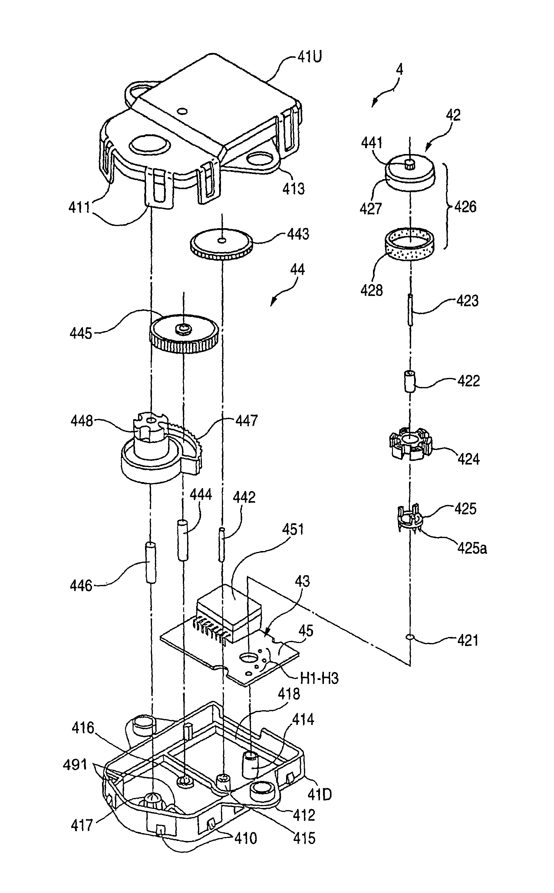
[0031]In the invention, the yoke of the rotor and the gear in the brushless motor are formed integrally with each other, using the resin, and these are supported on the rotation shaft in a fitted condition. Therefore, the number of the component parts of the rotor is reduced, and the time and labor, required for assembling the rotor, are reduced. As a result, the cost of the parts and the cost of the assembling operation are reduced, so that the low-cost design of the motor can be achieved. And besides, press-fitting margins for the purpose of press-fitting the relevant parts do not need to be provided on the rotation shaft, and therefore the axial dimension of the rotation shaft can be reduced, which is advantageous in achieving the compact design. Furthermore, the yoke and the gear are made of the resin, and therefore the lightweight design can be achieved, and this also prevents the vibration during the high-speed rotation, so that a rotation balance can be improved, thereby enhancing the rotation characteristics.
[0034]In the invention, before the
stator coil is mounted on the board, the core base is beforehand integrally connected to the core, and terminals of the coils are connected to the terminals, and then the terminals of the core base are connected to the board, thereby mounting the
stator coil on the board. With this construction, the
stator coil can be easily mounted on the board, and also the positioning of the stator coil relative to the board can be effected highly precisely by the core base, so that the stator coil can be stably and highly precisely mounted relative to the rotor.
[0035]In the invention, when the stator coil is fitted on the boss, the positioning of the stator coil is effected by the positioning means for positioning it in the circumferential and axial directions, and the stator coil is supported on the boss through the engagement means. Therefore, the mounting of the stator coil can be effected easily, and besides the stator coil can be highly precisely located relative to the boss, and can also be highly precisely located relative to the rotor mounted on the boss.

