Inlet guide vane bushing having extended life expectancy

a technology life expectancy, which is applied in the direction of sustainable transportation, mechanical equipment, machines/engines, etc., can solve the problems of inlet guide vane assembly considerable wear, and achieve the effect of reducing maintenance costs, improving the wear life of the bushing, and reducing maintenance costs

Inactive Publication Date: 2006-10-17
GENERAL ELECTRIC CO
View PDF19 Cites 19 Cited by
  • Summary
  • Abstract
  • Description
  • Claims
  • Application Information

AI Technical Summary

Benefits of technology

[0010]An advantage of the present invention is that the wear life of the bushing is improved by over 100%, which means that the mean time between replacement for the bushing has been doubled so that maintenance related to bushing wear in variable inlet guide vanes can be reduced, resulting in decreased maintenance costs.

Problems solved by technology

The frequent movement of the inlet guide vane assemblies in response to pilot requirements for power and due to engine vibrations results in considerable wear to the inlet guide vane assemblies, which are designed to accommodate wear.

Method used


Image

  • Inlet guide vane bushing having extended life expectancy
  • Inlet guide vane bushing having extended life expectancy
  • Inlet guide vane bushing having extended life expectancy

Examples


Embodiment Construction

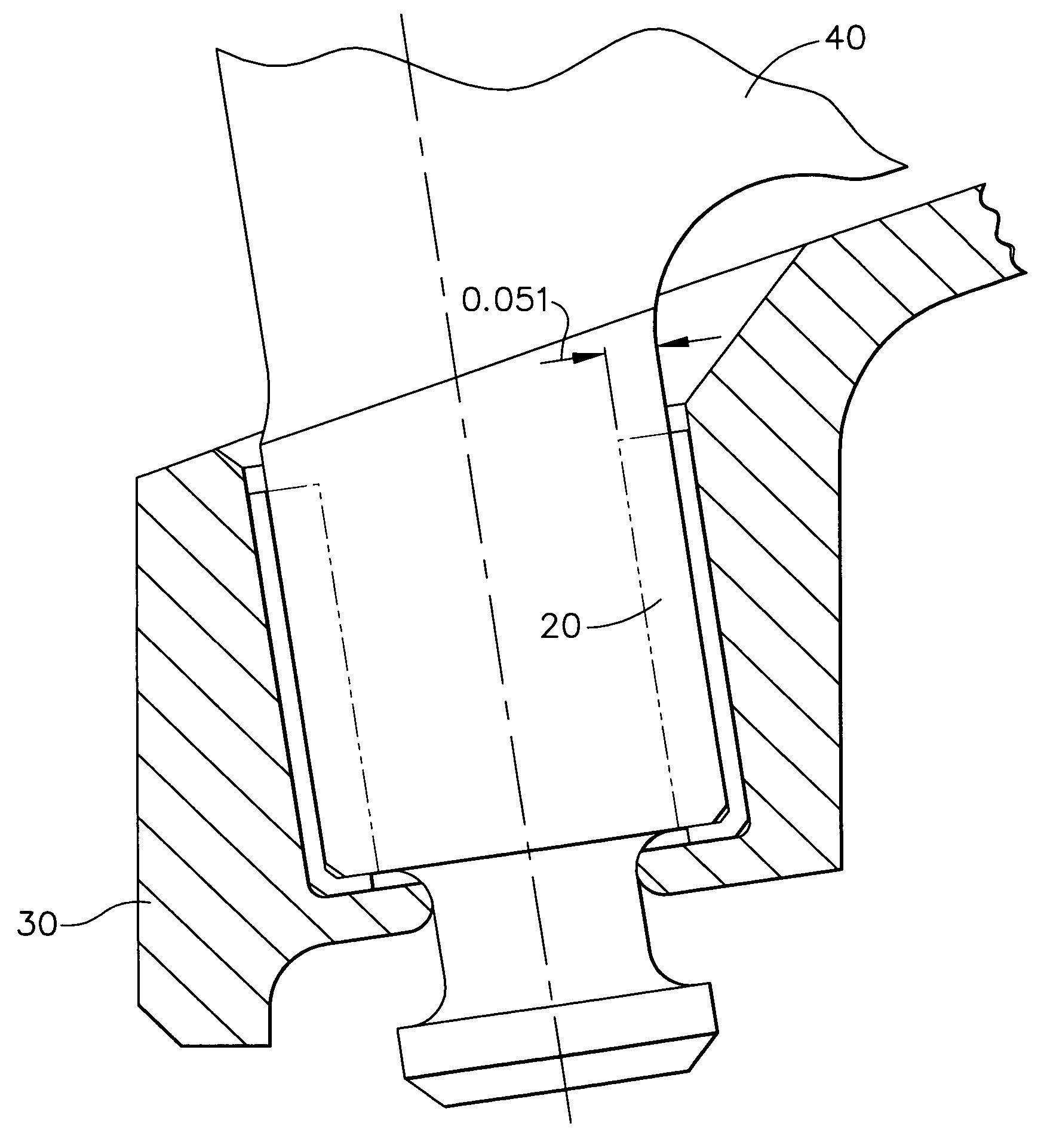
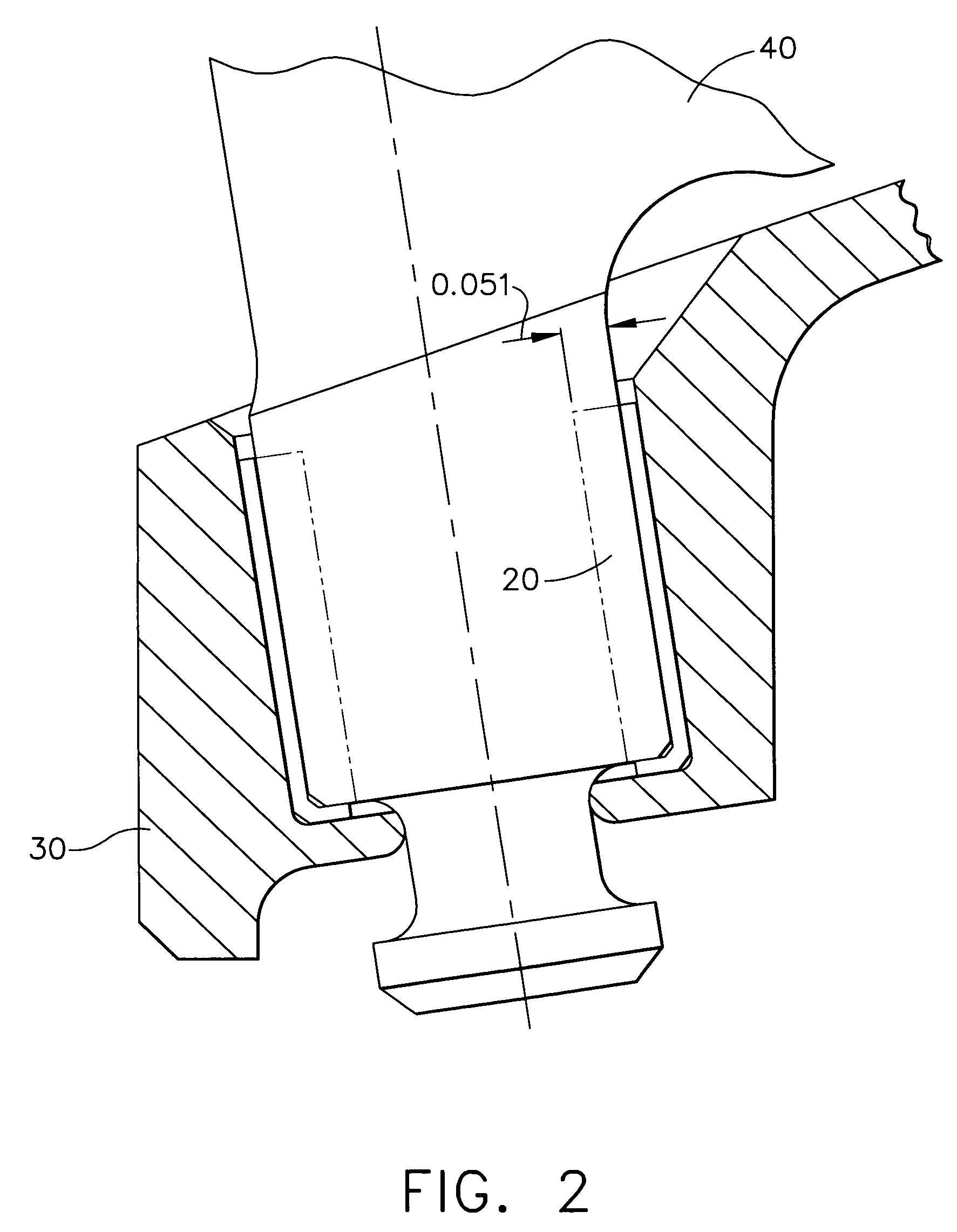
[0014]The present invention provides a bushing for use in an inlet guide vane assembly for a gas turbine engine. The bushing of the present invention has a preferred thickness of about 0.050 inches (50 mils). The manufacturing tolerance of such a bushing typically is ±0.002 inches. The bushing is manufactured from a high temperature composite material comprising carbon fiber reinforcing rods and a polymeric matrix. The polymeric matrix is preferably a polyimide resin matrix. The bushing may also additionally comprise filler material.

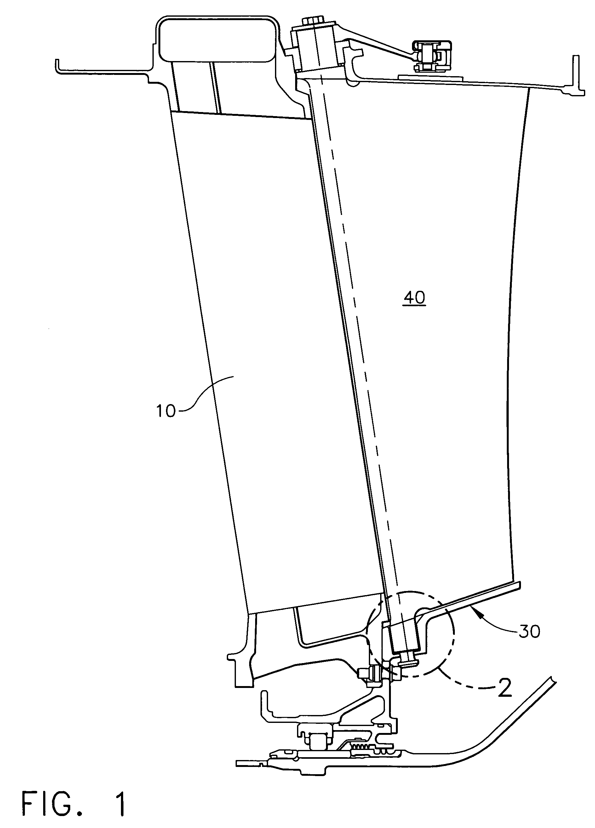
[0015]Referring now to FIG. 1 which is a typical inlet guide vane assembly 10 as may be found in a gas turbine engine. The bushing 20 extends between the shroud 30 and the vane 40. Surprisingly, and contrary to the well-established theories and teachings in the art, increasing the thickness of the bushing has actually improved the life of the bushing in this application.

[0016]Existing bushings having a thickness of 0.025 inches were tested in a fixture i...


PUM


Abstract

The present invention is a bushing for use in a gas turbine engine. The bushing is suitable for use in a gas turbine engine. The thickness of the bushing is increased to about 0.050 inches and the life expectancy of the bushing is at least doubled.

Description

CROSS-REFERENCE TO RELATED APPLICATIONS[0001]This Application is a continuation-in-part of Application Ser. No. 10 / 329,092, filed Dec.24, 2002, now abandoned.GOVERNMENT RIGHTS[0002]The United States Government may have certain rights in this invention pursuant to Government Contract No. F-33657-99-D-2050.FIELD OF THE INVENTION[0003]The present invention is directed to an improved inlet guide vane bushing for use on a high performance engine.BACKGROUND OF THE INVENTION[0004]A basic gas turbine engine for an aircraft includes a compressor that compresses air entering the engine, a combustor section where the compressed air is mixed with fuel and combusted as a hot gas, a turbine where energy is extracted from the hot gaseous stream to turn the engine shaft on which the compressor is mounted and an exhaust where the remaining hot gaseous stream is used to propel the aircraft. Turbine engines used to propel large aircraft such as passenger aircraft and transport aircraft may include a f...

Claims


Application Information

Patent Timeline
Patent Type & Authority Patents(United States)
IPC IPC(8): F16C33/20F01D17/16
CPCF01D17/162F16C33/201Y02T50/672Y10S384/911Y02T50/60
Inventor BRUCE, ROBERT WILLIAMDISTLER, TIMOTHY DAVID
Owner GENERAL ELECTRIC CO
Why Eureka
Try Eureka