Optical fiber connector assembly

a technology connector assemblies, applied in the field of optical fiber connectors, can solve the problems of insatiable use of such an optical fiber connector as described above, time-consuming and expensive connector or splicing technology, and low network cost and performance, and achieve the effect of reducing the traction for

Inactive Publication Date: 2006-10-17
LE SAVOIR DU GARDIEN
View PDF13 Cites 33 Cited by
  • Summary
  • Abstract
  • Description
  • Claims
  • Application Information

AI Technical Summary

Benefits of technology

[0014]In one aspect, the present invention is directed to a connector assembly for the connection of optical fibers, in association with a connector comprising a longitudinally extending body, said body comprising a first end and a second end, and said body having a conduit extending from said first end to said second end, and said body comprising a plurality of finger projections that extend longitudinally at each end of said first and second ends. The connector assembly includes a first collar circumferentially coupled to said end of said connector and a second collar circumferentially coupled to said second end of said connector. The connector assembly comprises a connector housing of four portions, which, when assembled, define a connector chamber for receiving and retaining a connector as aforesaid, when coupled with a collar. The four portions of the connector assembly are configured to exert a tractional force on the connector and connector collar when they are positioned in the connector chamber, by axial rotation of a first part of the connector housing relative to a second part. By the application of such tractional force on the connector, when positioned in the connector assembly, the conduit of the connector, due to amorphous phase deformation, is enlarged sufficiently, as a result of and to the extent of the amorphous and elastic capacity of deformation of the connector, in diameter to permit the entry of optical fibers to be connected. By the opposite axial rotation of the connector housing ends, there is a reduction of tractional force, permitting the collar and connector to return to a rest position, securing, by elastic capacity, the optical fibers and abutment of the ends of the optical fibers for transmission of optical signals.

Problems solved by technology

Splicing and connecting play a significant role in network cost and performance.
Current technologies for connectors or for splicing are time consuming and expensive, since they are difficult to miniaturize and to manipulate.
Use of such an optical fiber connector as described above is however not totally satisfactory as during the step of cooling the connector to allow it to return to its rest condition, there may be a tendency for the connector to push the ends of the optical fibers apart slightly.
Such a step is cumbersome to the easy and quick connection of optical fibers using an aforesaid connector.
This typically requires the use of certain operational skill by a technician that is carrying out the operation and is a hindrance to the quick and easy connection of optical fibers, to be used in any context where fibers are to be connected, including and in particular, in the context of a “last mile” connection where incoming fibers from an optical network are to be connected to an end use device, such as in a home, office, workplace and like environment.
However, this connector is cumbersome and difficult to use and does not allow for easy connection of optical fibers being connected since it comprises multiple pieces, such as a bush, a cage and a clamp.

Method used


Image

  • Optical fiber connector assembly
  • Optical fiber connector assembly
  • Optical fiber connector assembly

Examples


Embodiment Construction

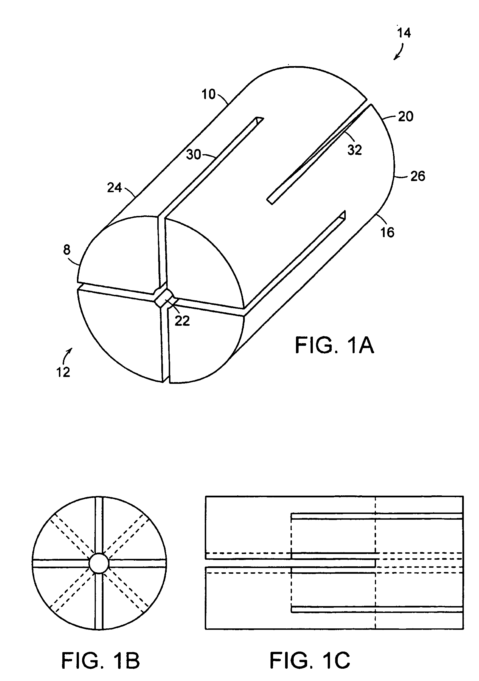
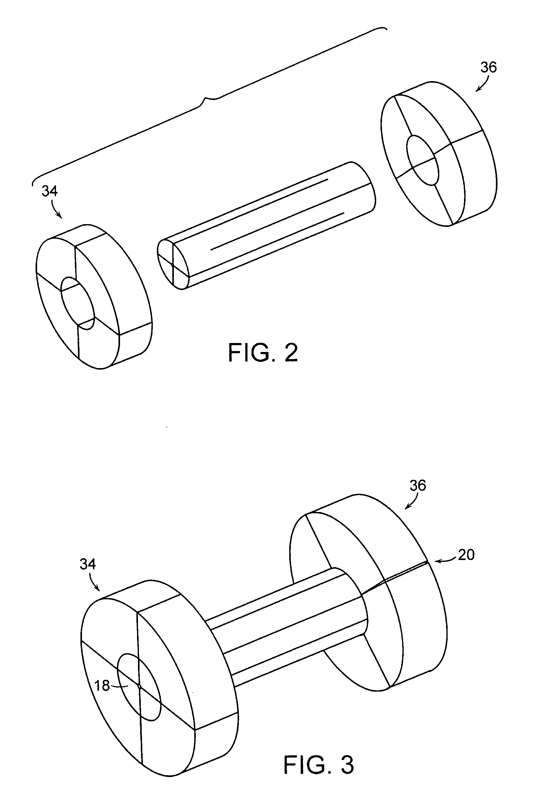
[0029]By reference to FIG. 1, is shown a connector 10 for use in an assembly in accordance with the present invention. Connector 10 may be used to connect the ends of a first optical fiber 12 and a second optical fiber 14 for optical signal transmission. Connector 10 has a connector body 16 which may be generally cylindrical. Connector body 16 has a generally first end 18 and a generally second end 20.

[0030]Connector body 16 also comprises a pass through conduit 22 which extends from first end 18 to the second end 20. The optical fibers 12 and 14 may be passed through the conduit 22 and secured therein, in abutment of the ends of the fibers, for optical signal transmission. Conduit 22 is configured and sized such that connector 10 applies a sufficient compressive force on optical fibers 12 and 14 to hold the fibers in abutment with each other, when the fibers are positioned in conduit 22. It will be understood that the compressive force must be sufficient to restrain the optical fib...


PUM


Abstract

The present invention is directed to an optical fiber (12,14) connector (10) comprising a longitudinally extending body (16), said body (16) comprising a first end (18) and a second end (20), and said body having a conduit (22) extending from said first end (18) to said second end (20), and said body (16) comprising a plurality of finger projections (24,26) that extend longitudinally at each end of said first (18) and second ends (20), the connector assembly (10) including a first collar circumferentially coupled to said first end (18) of said connector (10) and a second collar (36) circumferentially coupled to said second end (20) of said connector (10), the connector assembly (10) comprises a connector housing of four portions (38), which, when assembled, define a connector chamber for receiving and retaining a connector (10) as aforesaid.

Description

FIELD OF THE INVENTION[0001]The present invention relates to the field of optical fiber connectors and particularly to a connector assembly adapted for “last mile” use.BACKGROUND OF THE INVENTION[0002]In the field of photonics, optical fibers are used for the transmission of optical signals as well as for the linking of optical switches, waveguide grating devices, optical amplifiers, modules and the like. Optical transmission systems relying on photonics have been taking on greater importance, as optical signals are capable of carrying far larger amounts of information as compared to typical copper wire communication systems. For example, with the technology of Dense Wavelength Division Multiplexing (DWDM) and Demultiplexing it is possible to transmit multiple wavelengths in a single fiber, providing data capacities of 40 Gigabits per second and greater.[0003]Optical networks which require DWDM equipment and other such devices demand multiple amounts of splicers and connectors. Spli...

Claims


Application Information

Patent Timeline
Patent Type & Authority Patents(United States)
IPC IPC(8): G02B6/36G02B6/38
CPCG02B6/3806G02B6/3843G02B6/3854G02B6/38875
Inventor WEYNANT, ERICDEMISSY, DANIEL
Owner LE SAVOIR DU GARDIEN
Why Eureka
Try Eureka