
Reactor with multiple risers and consolidated transport

a technology of consolidated transport and reactors, applied in the field of reactors, can solve the problems of increasing increasing and increasing the difficulty of construction and maintenance of high aspect ratio transport fluid beds, so as to achieve the reduction of the width or diameter of the feedstock conversion reactor, the effect of reducing the height of the reactor

Active Publication Date: 2006-10-17
EXXONMOBIL CHEM PAT INC
View PDF80 Cites 34 Cited by
  • Summary
  • Abstract
  • Description
  • Claims
  • Application Information

AI Technical Summary

Benefits of technology

[0006]The present invention provides a solution to the currently existing need in the art by providing a hydrocarbon conversion apparatus which comprises a plurality of riser reactors from which the output is consolidated in one or more conduits for transport to a separation zone. By providing a plurality of riser reactors, the width or diameter of the feedstock conversion reactor can be reduced, and thus a desired aspect ratio can be maintained with its attendant closer approach to a desired, fully developed flow regime, at a reduced and more manageable reactor height. Further, the invention provides the proper aspect ratio for a given riser reactor without the need for multiple, independent reactor systems. By consolidating the output of the multiple risers in fewer, and preferably a single, transport conduit, the output can be directed to a single separation zone for processing.

Problems solved by technology

However, increasing fluid bed diameter, particularly in the transport regime, also requires increased reactor height.
Unfortunately, high aspect ratio transport fluid bed reactors are difficult and expensive to construct and maintain.
They are expensive because they must have a very large, heavy separation vessel at the top, often filled with heavy equipment, to capture and manage the flowing catalyst and reactor product.
As the reactor increases in height (aspect ratio), more expensive support structures may be required.
In certain areas of the world where inclement, especially windy weather occurs routinely, even more structural support is required, and certain aspect ratios are not economic.
With these multiple, complete and independent reactor systems come attendant multiplication of costs.

Method used


Image

  • Reactor with multiple risers and consolidated transport
  • Reactor with multiple risers and consolidated transport
  • Reactor with multiple risers and consolidated transport

Examples


Embodiment Construction

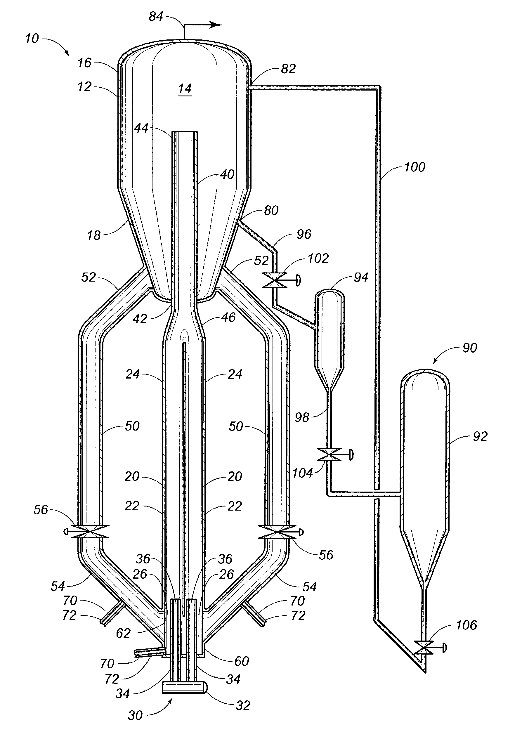
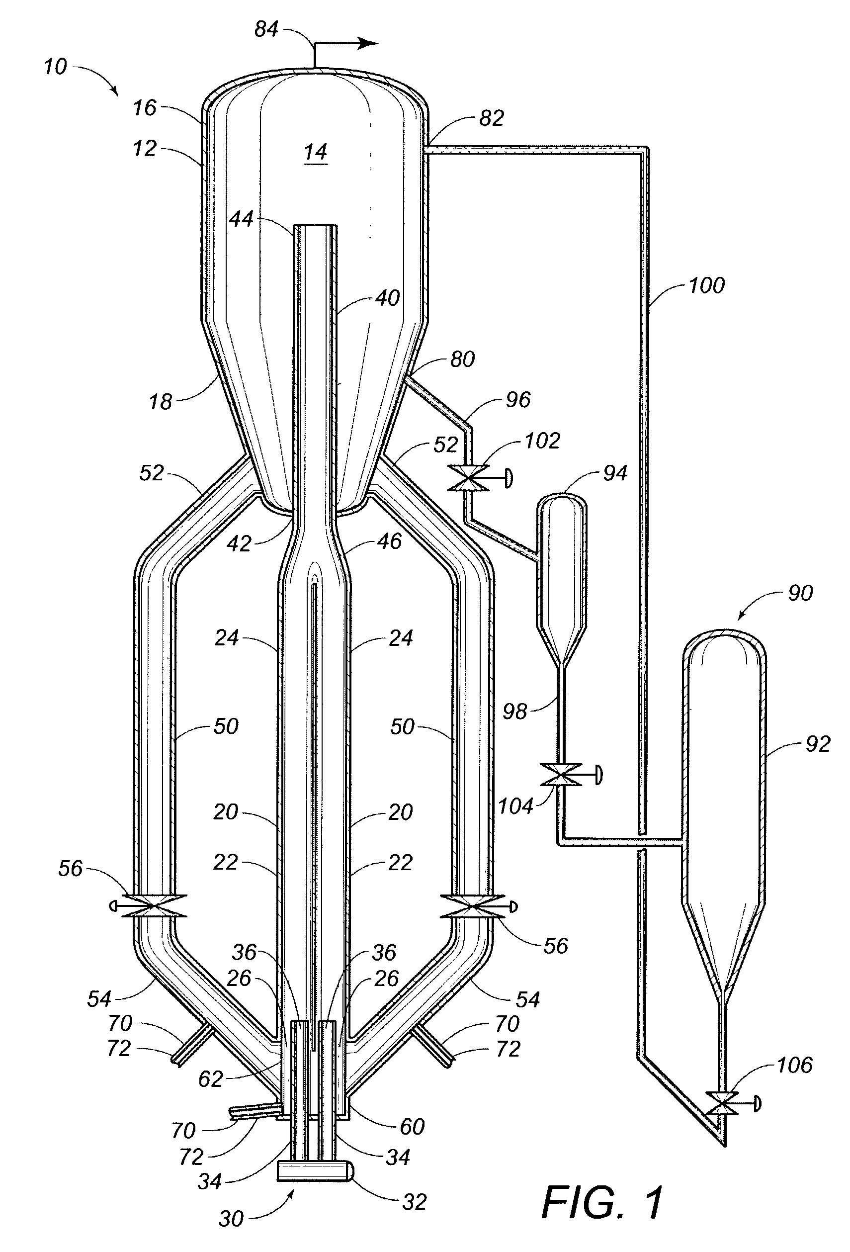
[0016]FIG. 1 presents a partial cross sectional view of a hydrocarbon conversion apparatus 10 of the present invention. The apparatus 10 comprises a plurality of riser reactors 20, a feed distributor 30, a transport conduit 40, a catalyst return 50 and a shell 12 including a separation zone 14.

[0017]With continuing reference to FIG. 1, the shell 12 forms a separation zone 14 in which a product of the hydrocarbon conversion reaction is separated from the catalyst which catalyzes the hydrocarbon conversion reaction. Shell 12 includes a first end 16 and a second end 18. The separation zone 14 may additionally contain one or more separation devices, not shown, which are used to separate the products from the catalyst. Useful separation devices are discussed below in association with the discussion of other embodiments of the present invention. Alternatively, the separation devices may be positioned externally to the separation zone 14, i.e., outside of the shell 12 of the hydrocarbon co...


PUM


Abstract

The present invention is directed to a hydrocarbon conversion apparatus. The apparatus comprises the following: a plurality of riser reactors, each of the riser reactors having a first end into which a catalyst can be fed and a second end through which the catalyst can exit the riser reactor; a separation zone provided to separate the catalyst from products of a reaction conducted in the hydrocarbon conversion apparatus; at least one transport conduit having a first end in fluid communication with at least two of the second ends of the riser reactors and a second end extending into the separation zone; and at least one catalyst return in fluid communication with the separation zone and the first ends of the riser reactors, the catalyst return being provided to transfer the catalyst from the separation zone to the first ends of the riser reactors.

Description

FIELD OF THE INVENTION[0001]The present invention relates to a reactor useful in hydrocarbon conversion processes and particularly in oxygenate to olefin conversion reactions. More particularly, the apparatus of the present invention relates to a hydrocarbon conversion apparatus having a transport conduit for consolidating and directing the output of multiple reactors to a separation zone.BACKGROUND OF THE INVENTION[0002]When converting a feedstock containing a hydrocarbon to a product in an industrial reactor, it is desirable to maximize the production of desired product or products, and to control, typically to minimize, the production of by-products. One type of reactor useful for conducting hydrocarbon conversion reactions is a fluidized bed reactor, wherein solid catalyst particles are suspended in a fluidized state during contact with the feedstock and other vapor materials. These types of reactors usually have a cylindrical reactor geometry. One method for reducing the produc...

Claims


Application Information

Patent Timeline
IPC IPC(8): B01J8/00B01J8/18F23C10/00F23C10/18B01J8/26B01J8/38B01J19/26C10G2/00C10G3/00
CPCB01J8/0055B01J8/26B01J8/388B01J19/26C10G2/344C10G3/49C10G3/57C10G3/62B01J2219/00038C10G2300/4093C10G2400/20Y02P30/20
Inventor BROOKHART, WALTER R.
Owner EXXONMOBIL CHEM PAT INC
Features
  • Generate Ideas
  • Intellectual Property
  • Life Sciences
  • Materials
  • Tech Scout
  • Unparalleled Data Quality
  • Higher Quality Content
  • 60% Fewer Hallucinations
Learn More