Ink jet recording element

a technology of recording element and ink jet, which is applied in the direction of thermography, duplication/marking methods, coatings, etc., can solve the problems of non-homogeneous coverage of ink in the ink receiving layer, and low optical density of printed images. achieve excellent dry time and image stability, improve image quality, and improve image quality

Inactive Publication Date: 2006-10-17
EASTMAN KODAK CO
View PDF13 Cites 0 Cited by
  • Summary
  • Abstract
  • Description
  • Claims
  • Application Information

AI Technical Summary

Benefits of technology

[0026]By use of the invention, an ink jet recording element is obtained that, when printed with dye-based inks, provides superior optical densities, good image quality and has an excellent dry time and image stability.

Problems solved by technology

However, there is a problem with such porous recording elements in that the optical densities of images printed thereon are lower than one would like.
Another problem with a porous recording element is that atmospheric gases or other pollutant gases readily penetrate the element and lower the optical density of the printed image causing it to fade.
Still another problem occurs from microcracking of the surface of the coated layer that leads to a non-homogeneous coverage of ink in the ink receiving layer.
However, there is a problem with this element in that it is not stable to light and exposure to atmospheric gases.
However, there is no specific teaching of a metal oxy(hydroxide) complex as described herein.
However, there is a problem with such elements in that they tend to fade when subjected to atmospheric gases, as will be shown hereafter.

Method used


Image

  • Ink jet recording element

Examples


example 1

Dye Stability Evaluation Tests

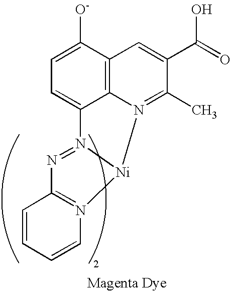
[0049]The dye used for testing was a magenta colored ink jet dye having the structure shown below. To assess dye stability on a given substrate, a measured amount of the ink jet dye and solid particulates or aqueous colloidal dispersions of solid particulates (typically about 10%–20.0% by weight solids) were added to a known amount of water such that the concentration of the dye was about 10−5 M. The solid dispersions containing dyes were carefully stirred and then spin coated onto a glass substrate at a speed of 1000–2000 rev / min. The spin coatings obtained were left in ambient atmosphere with fluorescent room lighting (about 0.5 Klux) kept on at all times during the measurement. The fade time was estimated by noting the time required for complete disappearance of magenta color as observed by the naked eye or by noting the time required for the optical absorption to decay to less than 0.03 of the original value.

[0050]

Comparative Coatings C-1 to C-13 (N...

example 2

Element 1

[0092]A coating composition was prepared from 20.9 wt. % of an aqueous dispersion of zirconium(oxy)hydroxyacetate (a 20 wt. % aqueous dispersion from Alfa Aesar, lot # D03K29; 0.005–0.01 μm particles), 41.8 wt. % of a fumed alumina solution (40 wt. % alumina in water, Cab-O-Sperse® PG003 from Cabot Corporation), 3.1 wt. % poly(vinyl alcohol) (PVA) (Gohsenol® GH-23 from Nippon Gohsei Co.), and 34.2 wt. % water. [The relative proportions of zirconia to alumina are 20 / 80, and the amount of PVA is 13.0 wt % of all solids]. The solution was metered to a slot-die coating apparatus and coated onto a stationary base support comprised of a polyethylene resin coated photographic paper stock, which had been previously subjected to corona discharge treatment, and dried to remove substantially all solvent components to form the ink receiving layer.

Element 2

[0093]This element was prepared the same as Element 1 except that the coating composition was 13.1 wt. % of Zr100 / 20 (a 20 wt. % aqu...


PUM

PropertyMeasurementUnit
particle sizeaaaaaaaaaa
sizeaaaaaaaaaa

Abstract

An ink jet recording element comprising a support having thereon an image-receiving layer, the ink jet recording element containing finely divided particulate material and a metal(oxy)hydroxide complex, Mn+(O)a(OH)b(Ap−)c.xH2O, wherein M is at least one metal ion; n is 3 or 4; A is an organic or inorganic ion; p is 1, 2 or 3; and x is equal to or greater than 0; with the proviso that when n is 3, then a, b and c each comprise a rational number as follows: 0≦a<1.5; 0<b<3; and 0≦pc<3, so that the charge of the M3+ metal ion is balanced; and when n is 4, then a, b and c each comprise a rational number as follows: 0≦a<2; 0<b<4; and 0≦pc<4, so that the charge of the M4+ metal ion is balanced.

Description

CROSS REFERENCE TO RELATED APPLICATIONS[0001]Reference is made to commonly assigned, co-pending U.S. patent applications:[0002]Ser. No. 10 / 180,184 by Bringley et al., filed of even date herewith entitled “Ink Jet Printing Method”;[0003]Ser. No. 10 / 180,638 by Sharma et al., filed of even date herewith entitled “Ink Jet Recording Element”;[0004]Ser. No. 10 / 180,373 Sharma et al., filed of even date herewith entitled “Ink Jet Recording Element”;[0005]Ser. No. 10 / 180,182 by Sharma et al., filed of even date herewith entitled “Ink Jet Recording Element”;[0006]Ser. No. 10 / 180,187 by Bringley et al., filed of even date herewith entitled “Ink Jet Printing Method” now U.S. Pat. No. 6,984,033;[0007]Ser. No. 10 / 180,395 by Bringley et al., filed of even date herewith entitled “Ink Jet Printing Method” now U.S. Pat No. 6,991,835; and[0008]Ser. No. 10 / 180,179 by Bringley et al., filed of even date herewith entitled “Ink Jet Recording Element”.FIELD OF THE INVENTION[0009]The present invention relat...

Claims


Application Information

Patent Timeline
Patent Type & Authority Patents(United States)
IPC IPC(8): B41M5/00B41M5/52
CPCB41M5/52B41M5/5218
Inventor SHARMA, KRISHAMOHANBRINGLEY, JOSEPH F.LANDRY-COLTRAIN, CHRISTINE
Owner EASTMAN KODAK CO
Why Eureka
Try Eureka