Ion source apparatus and method

a technology of ion source and cyclotron, which is applied in the direction of ion beam tubes, instruments, nuclear engineering, etc., can solve the problems of extended down time in isotope production, ion source replacement takes some time, and the life of ion source is typically limited, so as to improve the life and performance of ion sour

Active Publication Date: 2006-10-17
GENERAL ELECTRIC CO
View PDF16 Cites 85 Cited by
  • Summary
  • Abstract
  • Description
  • Claims
  • Application Information

AI Technical Summary

Problems solved by technology

An ion source typically has a limited lifetime and therefore requires periodic replacement.
However, since the cyclotron usually becomes radioactive during isotope production, it is necessary to wait for the radiation to decay to a safe level before starting the service.
Replacement of the ion source takes some time depending on the complexity of the ion source assembly as well as its accessibility.
As a result, every scheduled service for ion source replacement causes extended down time in isotope production.
Some drawbacks may exist in the design of the prior art ion source tube 200.
These and other drawbacks may exist in known systems and methods.

Method used


Image

  • Ion source apparatus and method
  • Ion source apparatus and method
  • Ion source apparatus and method

Examples


Embodiment Construction

[0018]Reference will now be made in detail to exemplary embodiments of the invention.

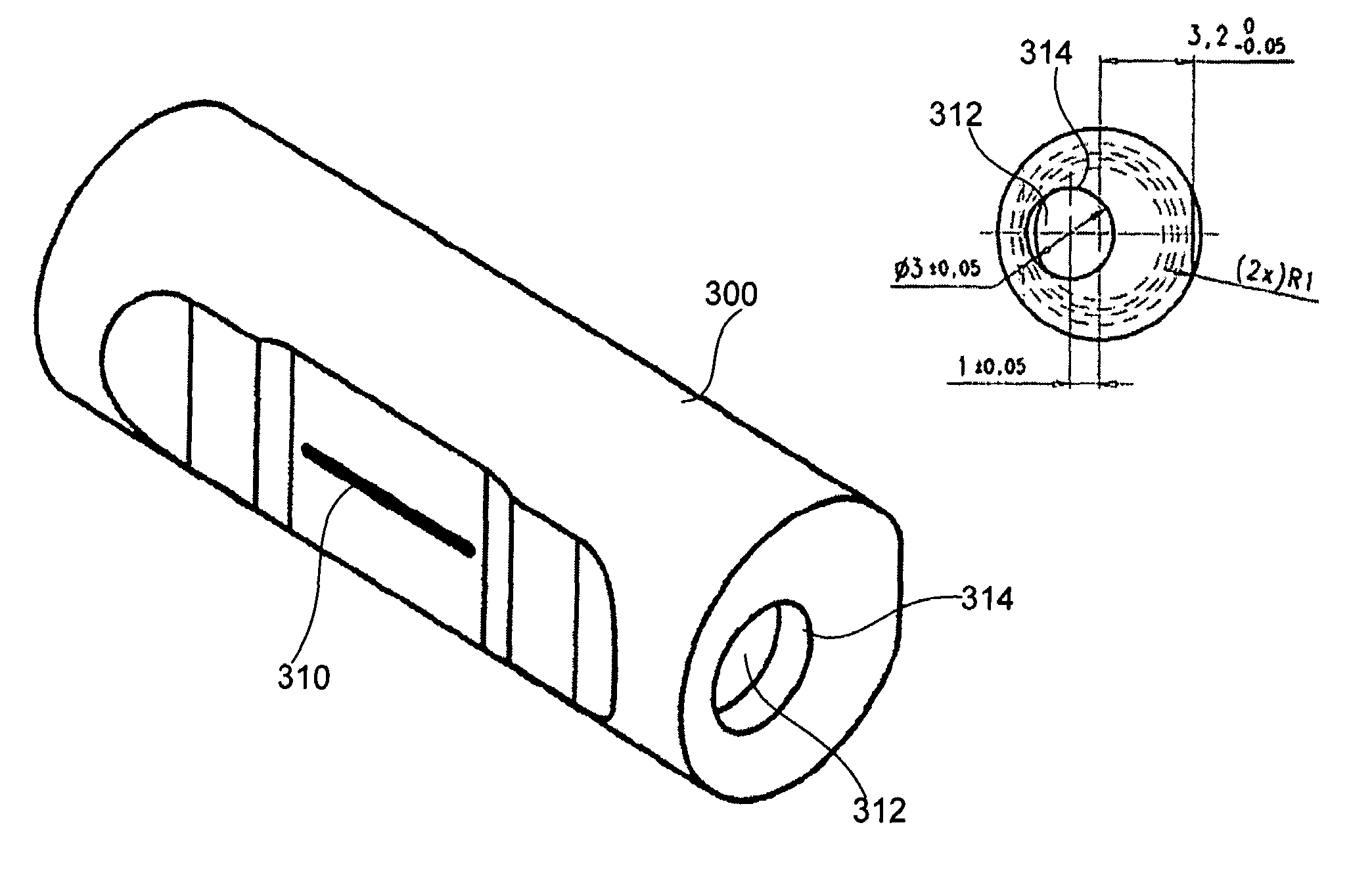
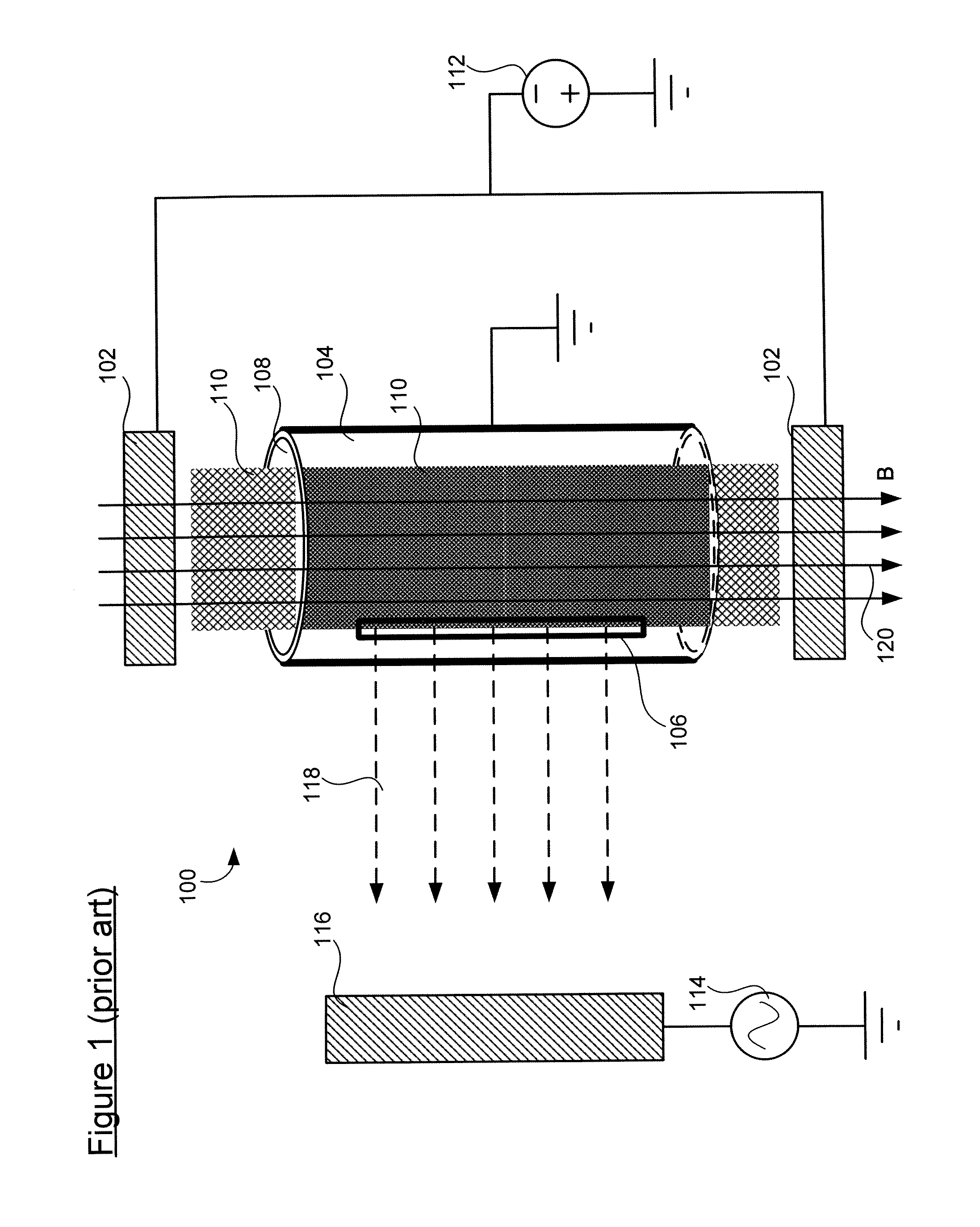
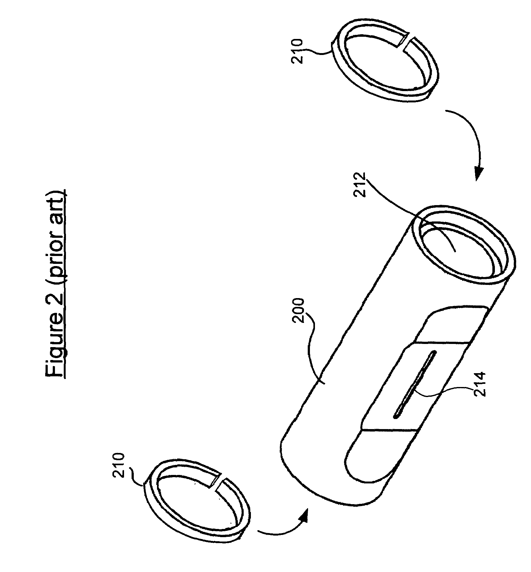
[0019]Referring to FIG. 8, there is shown a perspective view of an exemplary ion source tube 300 according to an embodiment of the invention. The ion source tube 300 may be used in a plasma-based ion source similar to the one shown in FIG. 1. A plasma discharge (not shown) may be sustained in or near the ion source tube 300. The ion source tube 300 may be made of metals (e.g., copper and tungsten) that are resistant to heat and the plasma discharge. As shown, the exemplary ion source tube 300 has a substantially cylindrical shape. There may be a slit opening 310 in the front side of the ion source tube 300 for extraction of ions. There may be an end opening 314 in the end of the ion source tube 300 to accommodate a flow of gas ingredient(s) and to help define the shape and position of the plasma discharge. Inside the ion source tube 300, there may be a pre-shaped cavity 312 that further defines the ...


PUM


Abstract

The invention relates to a method and apparatus that can improve the lifetime and performance of an ion source in a cyclotron. According to one embodiment, the invention comprises an ion source tube for sustaining a plasma discharge therein. The ion source tube comprises a slit opening along a side of the ion source tube, wherein the slit opening has a width less than 0.29 mm. The ion source tube also comprises an end opening in an end of the ion source tube. The end opening is smaller than an inner diameter of the ion source tube and is displaced by 0–1.5 mm from a central axis of the ion source tube toward the slit opening. The plasma column is displaced 0.2 to 0.5 mm relative the slit opening. The ion source tube comprises a cavity that accommodates the plasma discharge. The invention also relates to a method for making an ion source tube.

Description

BACKGROUND OF THE INVENTION[0001]The present invention relates generally to the field of cyclotron design for radiopharmacy and more particularly to a method and apparatus that can improve ion source lifetime and performance.[0002]Hospitals and other health care providers rely extensively on positron emission tomography (PET) for diagnostic purposes. PET scanners can produce images which illustrate various biological process and functions. In a PET scan, the patient is initially injected with a radioactive substance known as a PET isotope (or radiopharmaceutical). The PET isotope may be 18F-fluoro-2-deoxyglucose (FDG), for example, a type of sugar which includes radioactive fluorine. The PET isotope becomes involved in certain bodily processes and functions, and its radioactive nature enables the PET scanner to produce an image which illuminates those functions and processes. For example, when FDG is injected, it may be metabolized by cancer cells, allowing the PET scanner to create...

Claims


Application Information

Patent Timeline
Patent Type & Authority Patents(United States)
IPC IPC(8): H01J7/24
CPCH01J27/08H05H13/00
Inventor NORLING, JONAS OVEBERGSTROM, JAN-OLOF
Owner GENERAL ELECTRIC CO
Why Eureka
Try Eureka