
Dimmable ballast with resistive input and low electromagnetic interference

a technology of resistive input and electromagnetic interference, applied in the field of power converters, can solve the problems of high-performance and expensive components, still not as popular as the conventional magnetic ballast, and the trade-off between cost and reliability of the electronic ballast, so as to reduce the noise of high frequency switching, reduce losses, and reduce the effect of high frequency switching

Active Publication Date: 2006-10-17
THE UNIVERSITY OF HONG KONG
View PDF9 Cites 0 Cited by
  • Summary
  • Abstract
  • Description
  • Claims
  • Application Information

AI Technical Summary

Benefits of technology

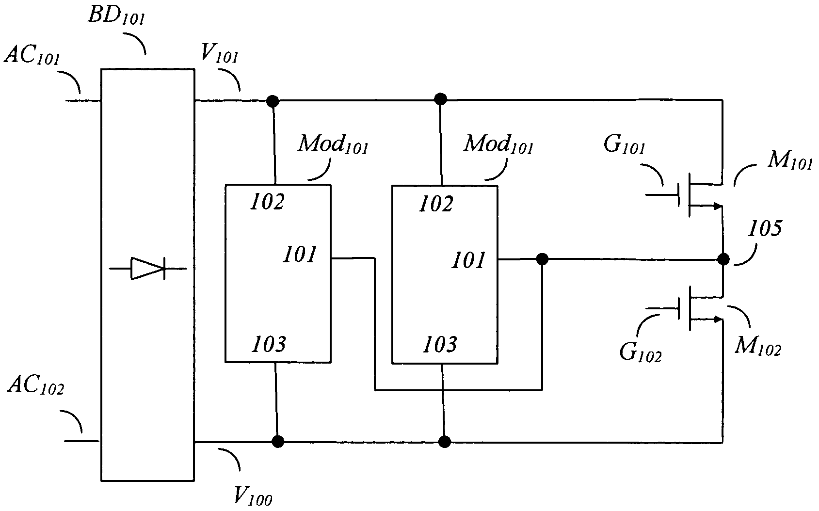
The present invention is a switching converter that delivers a pre-designed power to a gas discharge lamp, which is proportional to the input voltage squared. The converter uses capacitors and a lamp load to automatically correct power factor and deliver energy to the lamp in packets controlled by the switching frequency. The converter is dimmable by an external triac phase control dimmer and can adjust power delivery to the load by switching frequency. It eliminates the need for a bulk converter, reduces losses at high frequency switching, and reduces high frequency switching noise. The converter topology is simple with input power factor correction characteristics without an additional converter.

Problems solved by technology

However, it is still not as popular as the conventional magnetic ballast.
Very often high-performance and expensive components are required in order to meet these regulations.
For example, high voltage electrolytic bulk capacitor are usually needed in a ballast circuit, but the life time of most high voltage electrolytic capacitor is 2,000 hours at rated condition, which is only half the life time of a tube type fluorescent lamp.
So there is very tough trade off between cost and reliability of an electronic ballast.
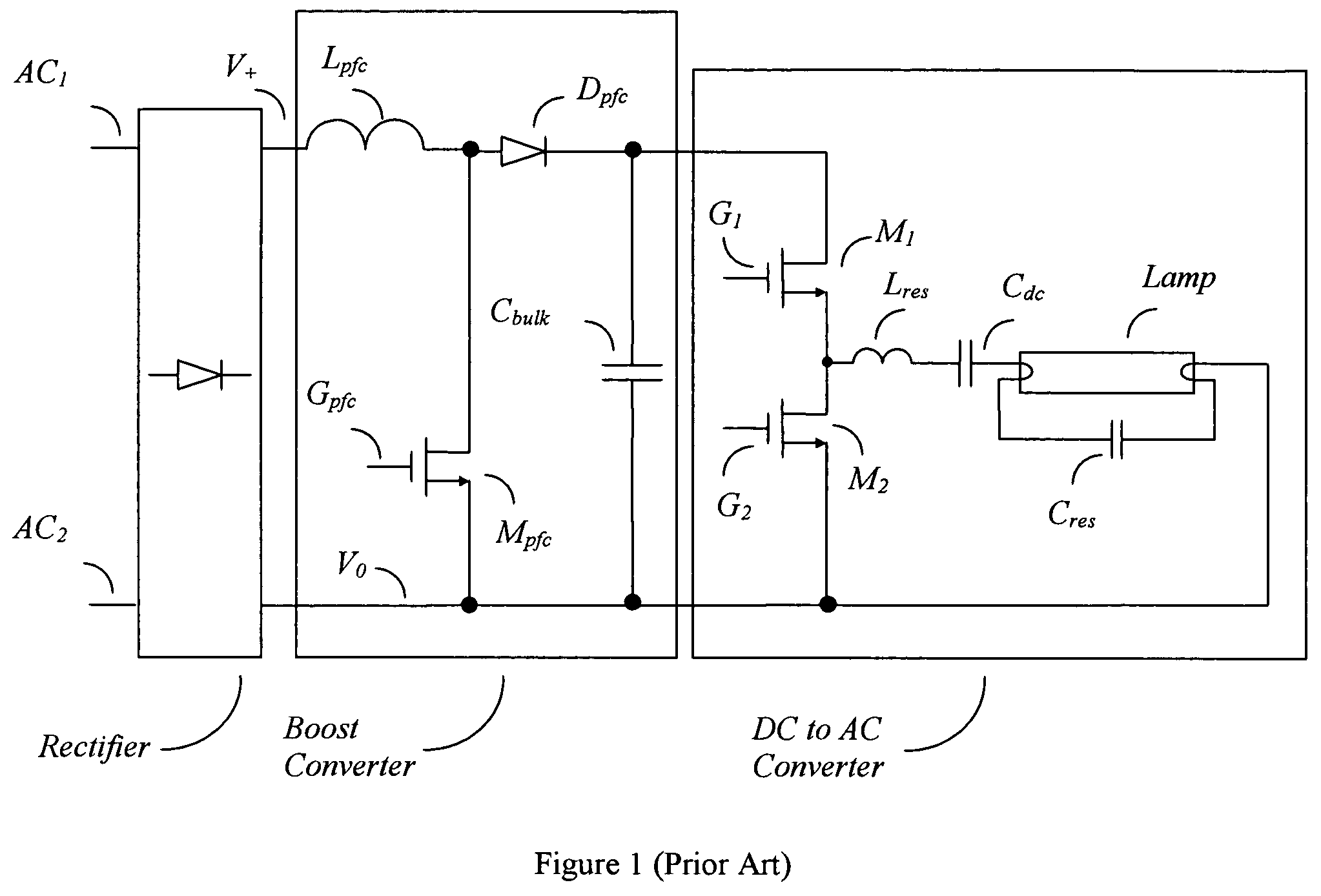
The major drawback of this prior art is the sensitivity to component variations because resonant is key of the operation.
This calls for more complicated circuits in the ballast.
This type of control method cannot be very stable because the resonant circuit characteristics is very sensitive and changeable.
Many complex circuits are needed, together with the power factor corrector front end the final product is not cost competitive.
In U.S. Pat. No. 6,348,767 Chen et al use two resonate circuit and connect the lamp loading to input side to provide a small continuous current flow to hold the triac dimmer on the input side but it produces poor power factor.
This produces excessive voltage stresses on the components in the circuit.

Method used


Image

  • Dimmable ballast with resistive input and low electromagnetic interference
  • Dimmable ballast with resistive input and low electromagnetic interference
  • Dimmable ballast with resistive input and low electromagnetic interference

Examples


Embodiment Construction

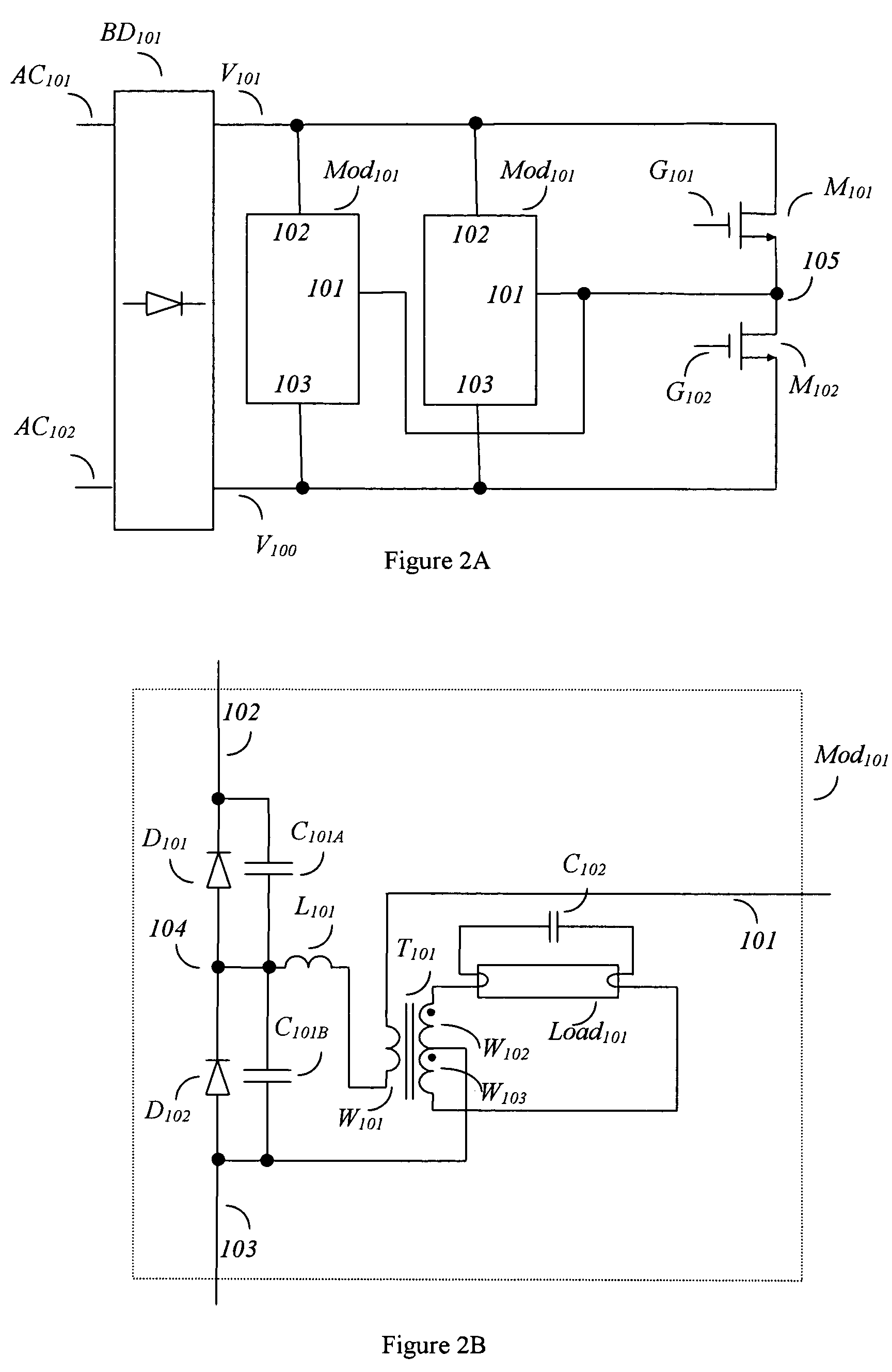
[0022]The principle of the invention is described herein. A set of complementary electronic switches connected to a voltage source generates a plurality of pulses which are then injected into one or more constant power modules. Each module comprises of two series capacitors coupled to the power supply rail. Each capacitor has an anti-parallel diode. The junction of the capacitor is coupled to a load and then the injection of pulses. Effectively the capacitors are charged and discharged through the load. When the capacitor is charged, energy will be delivered to the load. Consider the case of charging a capacitor from 0V. The parameters are capacitance C with series load Rs and a voltage source Vs. Let the energy expended on the series load Rs during charging be ERs—c. The total energy deliver to the whole circuit is the integration of voltage Vs and the current iin with respect to time which is equal to the energy stored in the capacitor and energy expended on the series load, as re...


PUM


Abstract

An AC to AC power conversion apparatus with constant power feeding characteristics to fluorescent lamp or FD lamp is described. The constant power characteristic is achieved by discontinuous mode operation of capacitor coupled in series with the load. Packets of energy are pumped out to the load in each switching cycle, regardless of the resonant characteristics. The dependence of the input power on the square of the supply voltage make the input resistive and produces good power factor automatically. The lamp load is dimmable by external phase control dimmer like resistive incandescent lamps. Multiple lamp loads with different power rating can be integrated by adding more sets of said capacitors and associated components.

Description

CROSS REFERENCE[0001]This application claims the benefit of U.S. Provisional Application No. 60 / 518,880 filed Nov. 10, 2003.FIELD OF THE INVENTION[0002]This invention relates to the field of power converters, in particular to the field of AC to AC conversion for ballast or gas discharge lamps such as fluorescent lamp, cold cathode fluorescent lamp or HID lamps. This converter has resistive input characteristic which produces high power factor and is dimmable by an external phase-controlled dimmer.BACKGROUND OF THE INVENTION[0003]Electronic ballast is widely used because of its advantages of high efficiency, energy saving and compact size. However, it is still not as popular as the conventional magnetic ballast. This is because electronic ballasts are often compared directly with magnetic ballast, both in terms of performance and cost. An electronic ballast has to meet many regulations for lighting apparatus such as those for input harmonic current, power factor, total harmonic disto...

Claims


Application Information

Patent Timeline
Patent Type & Authority Patents(United States)
IPC IPC(8): H05B37/02H05B41/28H05B41/282H05B41/392
CPCH05B41/28H05B41/2827H05B41/3924
Inventor POON, FRANKI NGAI KITPONG, MAN HAYLIU, JOE CHIU PONG
Owner THE UNIVERSITY OF HONG KONG
Learn More