Regulated, symmetrical crystal oscillator circuit and method

a crystal oscillator and symmetrical technology, applied in the field of oscillators, can solve the problems of affecting the overall stability of the crystal, and achieve the effect of improving the stability of the crystal

Active Publication Date: 2006-10-17
MONTEREY RES LLC
View PDF8 Cites 113 Cited by
  • Summary
  • Abstract
  • Description
  • Claims
  • Application Information

AI Technical Summary

Benefits of technology

[0011]The problems outlined above are in large part solved by an improved oscillator that, preferably, involves a crystal. The oscillator operates with minimum power into the crystal, or other resonant circuit, for a given amplitude, and also preferably diminishes any stimulation of unwanted harmonic modes of oscillation within the resonant circuit. The improved oscillator utilizes an oscillator amplifier that produces symmetrical current and voltage values within and across the nodes to which the crystal is connected. The symmetrical current and voltage values stimulate the crystals within a linear region of weak inversion of the amplifier transistors and, therefore, minimizes stimulation of harmonic modes of oscillation.
[0012]The improved oscillator avoids any semiconductor fabrication (i.e., process) dependence for regulating the amplitude of oscillation, as in many conventional systems. Moreover, the improved oscillator is yet fairly simple in structure and number of active components relative to the complex, conventional regulation systems that oftentimes use rectification and filtering. According to one embodiment, the oscillator amplifier is a modified form of a Pierce amplifier. The present amplifier is a symmetrically formed Pierce-type amplifier with a gate terminal of one transistor connected to one node, and a drain terminal of a series-connected second transistor connected to the other node. Thus, while a transistor is arranged between the pair of nodes, a second transistor is implemented in the improved Pierce-type amplifier configuration hereof. To promote symmetry, a mirrored pair of transistors and a diode-connected transistor are also used to ensure that the currents sourced from and sunk into the crystal via, for example, the XOUT node of the crystal are nearly equal and, thus, symmetrical across differing amplitude voltage ranges and across most semiconductor fabrication process corners.
[0013]According to one embodiment, the symmetrical Pierce-type oscillator amplifier hereof operates at maximum gain until the amplitude measured across the nodes exceeds a setpoint. A peak detector is used to determine a peak voltage value for the amplitude across the nodes. A controller circuit coupled to the peak detector then compares the peak voltage value against a predetermined voltage value or setpoint value to decrease a bias current if the peak voltage is greater in absolute magnitude than the predetermined voltage value. By decreasing the bias current through the Pierce-type amplifying transistor, the amplifier is maintained in the linear range and harmonic excitation and distortion is minimized. The oscillator amplifier thereby has an output node that can be coupled to the crystal, wherein the controller is used to adjust the bias current that is forwarded into the output node in order to regulate gain of the amplifier, and also regulate the resulting amplitude into the crystal. The regulated gain is sustained at a minimum needed to maintain oscillations within the crystal, preferably at the resonant frequency of that crystal.
[0015]The combination of the first transistor, second transistor, diode-coupled transistor, and a third and fourth transistors form an improved Pierce-type oscillator circuit that maintains symmetry of voltage and current values sent into the resonant circuit. In addition to the predetermined voltage value, a second predetermined voltage value can be established of less absolute magnitude than the predetermined voltage value. As the output from the oscillator amplifier increases during start-up operations, it is not until the output amplitude exceeds the second-predetermined voltage value will the output be enabled. In this fashion, spurious initial start-up harmonic components can be eliminated while maintaining maximum gain from the amplifier until such time as the peak voltage exceeds the predetermined value. Once the peak detector determines the excess voltage, then the amplifier will be regulated back into its linear range, and the amplitude output from the amplifier will be regulated to its optimal range.

Problems solved by technology

The non-linear effects and resulting induced harmonics within the crystal predominate if the transistors operate outside a weak inversion range and, thus, within what is known as the “saturation range.” If operated in the non-linear regions of strong inversion or saturation, the overall stability of the crystal will be negatively impacted.

Method used


Image

  • Regulated, symmetrical crystal oscillator circuit and method
  • Regulated, symmetrical crystal oscillator circuit and method
  • Regulated, symmetrical crystal oscillator circuit and method

Examples


Embodiment Construction

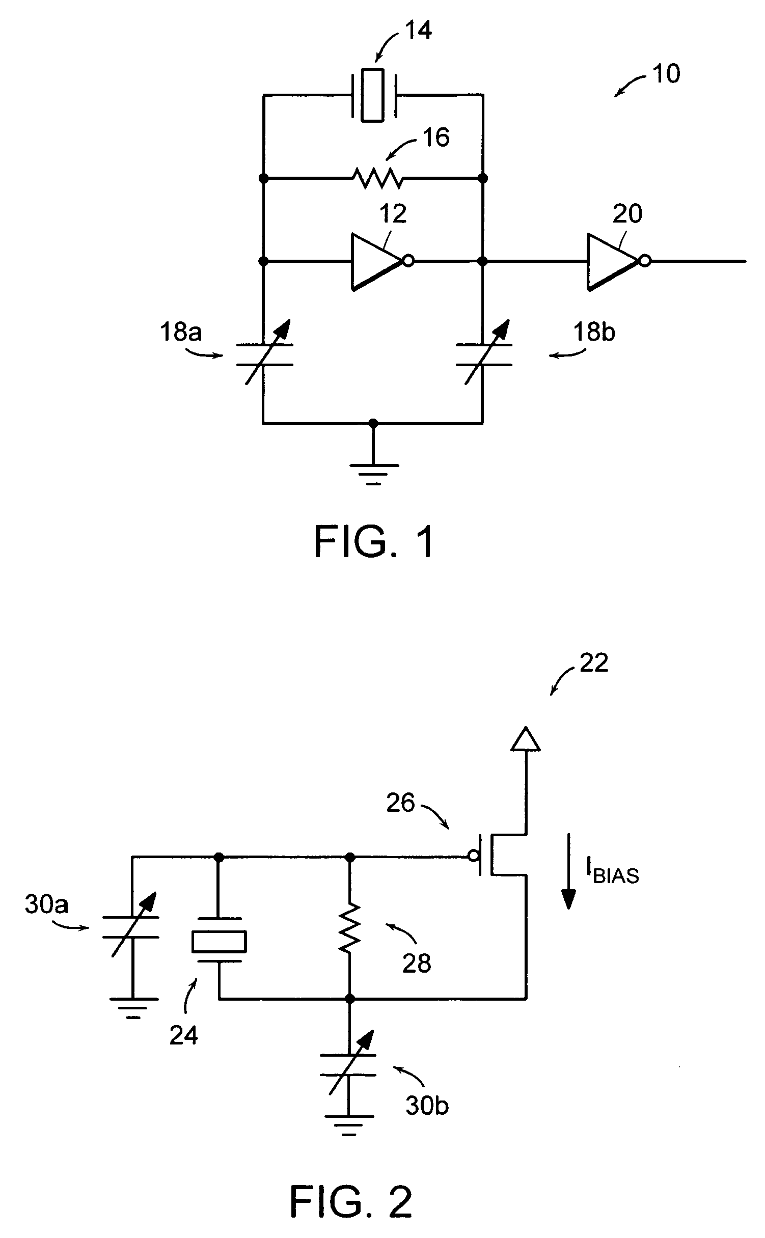
[0028]Turning now to the drawings, FIG. 1 illustrates one form of a crystal oscillator 10. While it is recognized that there are numerous types or forms of crystal oscillators, oscillator 10 involves an inverter 12 placed between nodes of a piezo-electric crystal 14. A feedback resistor 16 can also be connected between the oscillator nodes to bias those nodes to an appropriate voltage differential. The frequency of oscillation can be varied if needed by adjusting the capacitance value within the adjustable capacitors or varactors 18a and 18b, to “pull” the frequency of the quartz-crystal oscillator. If needed, only one varactor may be used with the other capacitance fixed. The resulting oscillator circuit 10 is oftentimes referred to as a voltage-controlled crystal oscillator, which combines the good-to-excellent stability of crystal oscillators with the tunability of LC oscillators. The crystal oscillator can be tuned by slightly adjusting the capacitance value of the varactor. If,...


PUM


Abstract

An oscillator circuit is provided that is preferably a crystal oscillator, where voltage placed across the crystal is regulated. The regulated voltage or amplitude of the cyclical signal across the crystal is monitored and maintained through a regulation circuit that measures a peak voltage across the crystal. Once the peak voltage exceeds a predetermined setpoint value, then a controller within the regulation circuit will reduce a biasing current through an amplifying transistor within the amplifier coupled across the crystal input and output nodes. By regulating the biasing current, gain from the amplifier is also regulated so that unwanted non-linearities and harmonic distortion is not induced within the crystal to cause frequency distortion and unwanted modes of oscillation within the crystal. The amplifier is preferably symmetrical in that the amplifier sources and sinks equal current to reduce unwanted peaks at the negative or positive half cycles of the sinusoidal signal.

Description

BACKGROUND OF THE INVENTION[0001]1. Field of the Invention[0002]The present invention relates to an oscillator and, more specifically to a crystal oscillator having a regulated, symmetrical amplitude to minimize non-linearities and deleterious stimulation of harmonic modes of oscillation.[0003]2. Description of the Related Art[0004]The following descriptions and examples are not admitted to be prior art or conventional by virtue of their inclusion within this section.[0005]Within nearly every electronic subsystem is some sort of generator that produces cyclical waveforms. The waveform generator is oftentimes referred to as an oscillator for producing regular oscillation signals. Depending on the application, an oscillator can be used simply as a source of regularly spaced pulses or clock signals. Oscillators are oftentimes rated depending on their stability and accuracy, frequency adjustability (i.e., tunability), and power consumption.[0006]There are numerous types of oscillators i...

Claims


Application Information

Patent Timeline
Patent Type & Authority Patents(United States)
IPC IPC(8): H03B5/36H03B1/00H03L1/00H03L5/00
CPCH03L5/00H03B5/04H03B5/36H03B2200/0012
Inventor BRENNAN, AARONSTIFF, JONATHONMCMENAMY, MIKE
Owner MONTEREY RES LLC
Why Eureka
Try Eureka