
Modulation of the resonant frequency of a circuit using an energy field

Inactive Publication Date: 2006-10-17
INTERMEC IP
View PDF61 Cites 42 Cited by
  • Summary
  • Abstract
  • Description
  • Claims
  • Application Information

AI Technical Summary

Benefits of technology

[0016]Another object of this invention is an improved, reusable RF tag that creates a dependable and easy to discriminate signal at the base station.

Problems solved by technology

When the tag is in the RF field, the tag's absorption can lead to a change in the tank circuit current of the base station and a power dip in a receiving coil.
Thus, they cannot give any information regarding the item's identification and are useful only for anti-theft applications.
At this stage, the tag is no longer usable and has been permanently destroyed.
Also, using this apparatus, the remanent state of ferroelectrics tends not to be very stable for long periods of time.
The disadvantage is that the item or person is subject to high r.f. fields during interrogation.
Also, the range of frequencies that needs to be scanned is necessarily large.
This makes detection difficult since the requirement to scan a large band of frequencies puts a strong demand on the flat response of the detector circuit.
On the other hand, when the hard magnet is demagnetized, the RF field results in hysteresis losses in the soft material which lowers the Q of the circuit.
While this constitutes a reusable tag, the change in Q tends to be small and thereby some what more difficult to distinguish from other effects that attenuate the absorption.
The tag absorption occurs twice with every complete sweep cycle resulting in a negative dip in the oscillator circuit.

Method used


Image

  • Modulation of the resonant frequency of a circuit using an energy field
  • Modulation of the resonant frequency of a circuit using an energy field
  • Modulation of the resonant frequency of a circuit using an energy field

Examples


Embodiment Construction

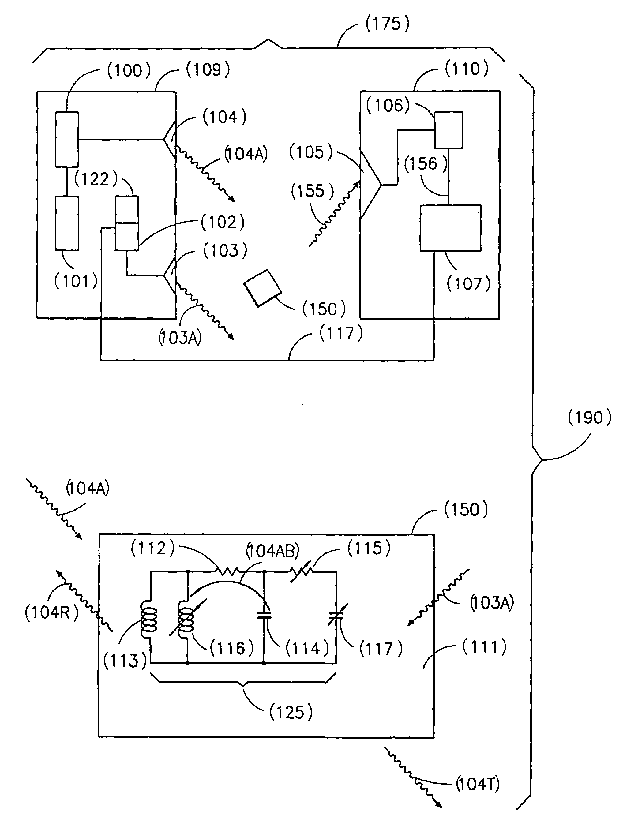
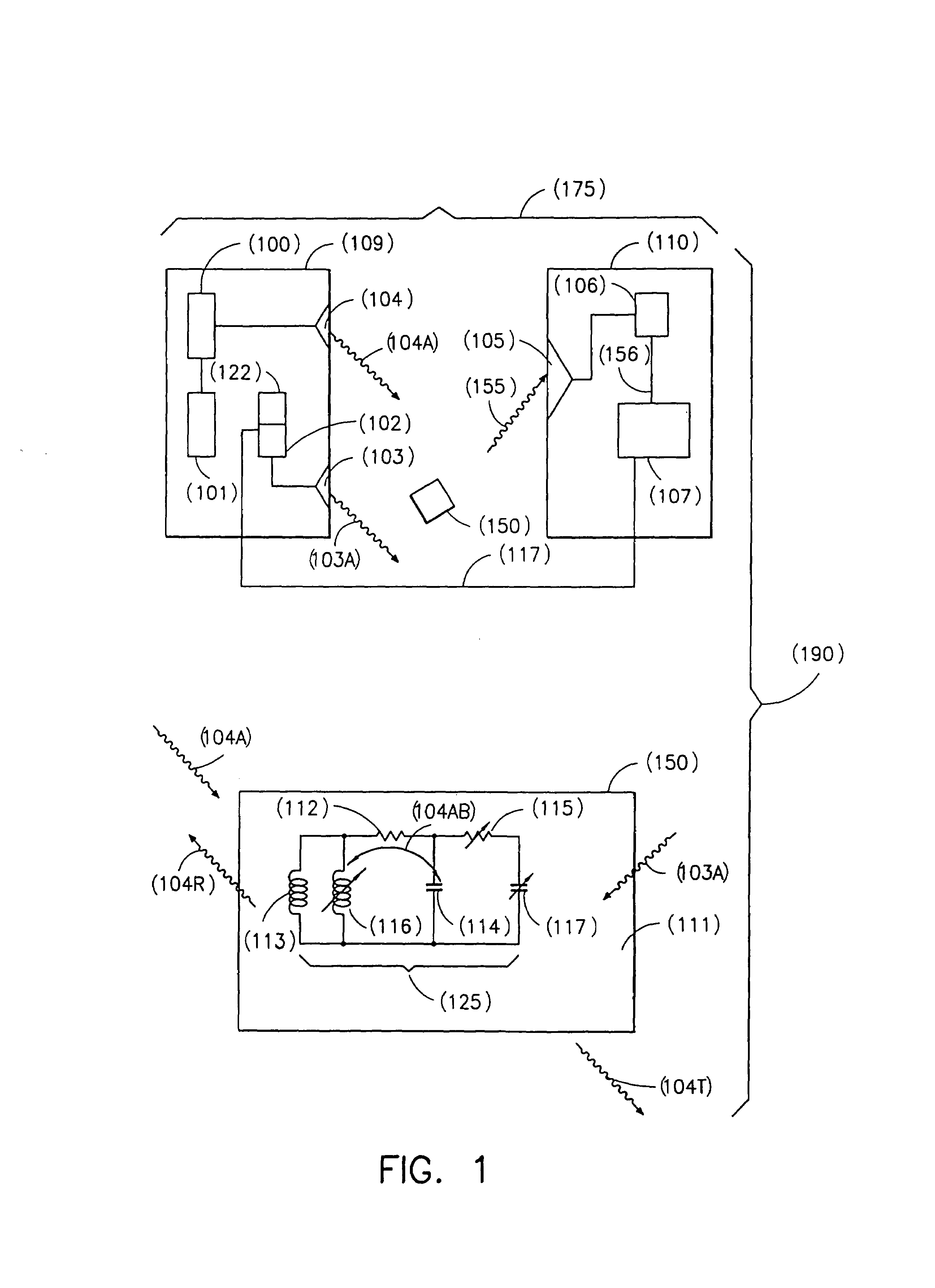
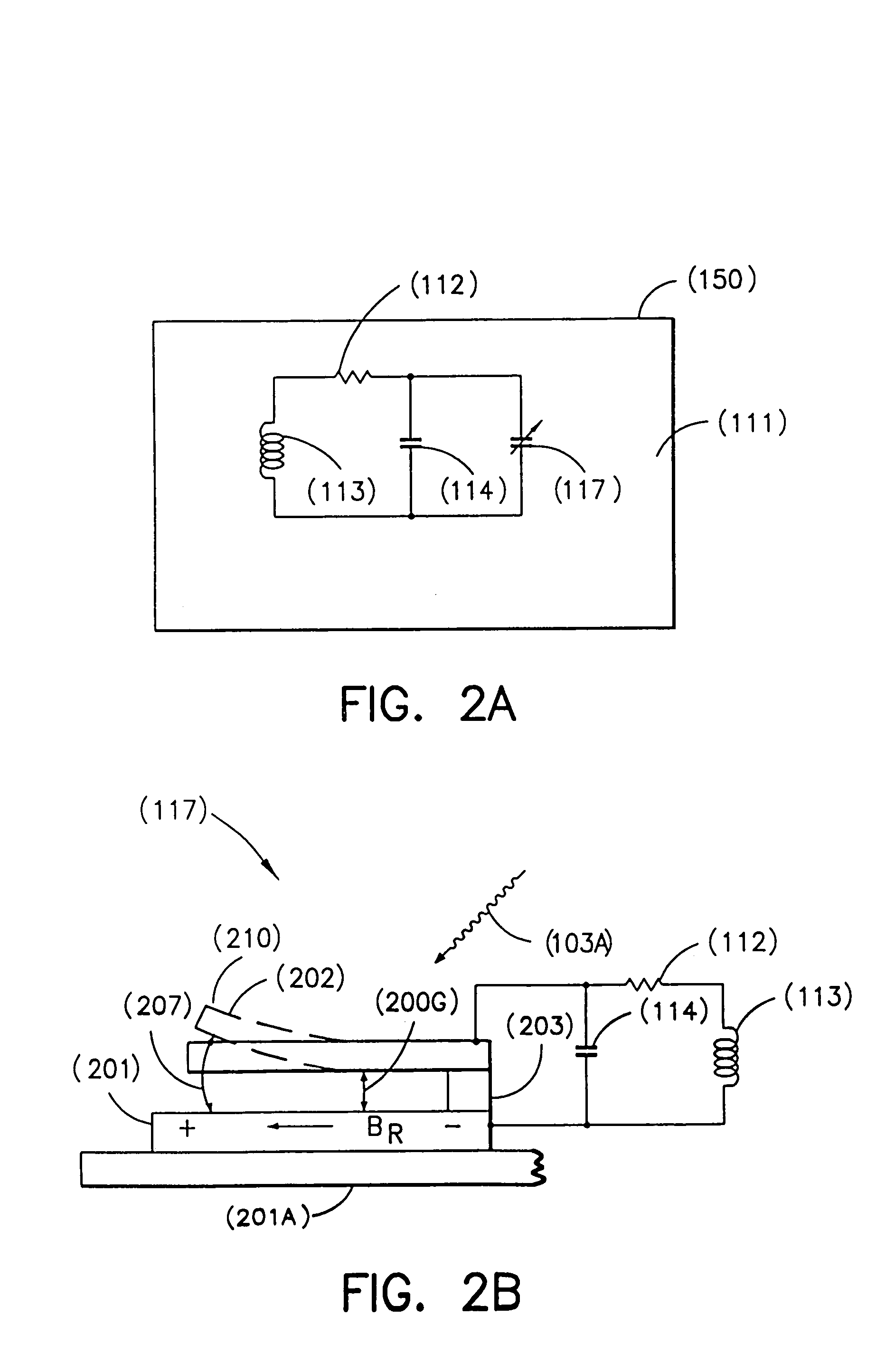
[0050]The present system (190) shown in FIG. 1 includes a novel transponder / tag (150) comprising a resonant circuit (125). The resonant circuit (125) has the fixed components of resistance, R (112), inductance L (113), and capacitance C (114) and one or more variable components of resistance R (115), inductance L (116), and / or capacitance C (117) which may be modified by an external modulating signal (103A). In addition, the system (190) includes a base station (175), provided for interrogating the resonant circuit (125), used as a transponder and / or an RF tag (150).

[0051]The base station (175) includes a transmitter (109) for transmitting the RF carrier signal (104A) and the modulating signal (103A) and a receiver (110) for receiving and demodulating the modulated carrier signal (155), i.e., the carrier signal (104A) modulated with the modulating signal (103A) by the transponder / tag 150.

[0052]The transmitter (109) comprises an RF carrier generator (101), RF carrier amplifier (100),...


PUM


Abstract

A transponder has a resonant RLC circuit with one or more electromagnetic energy storage components that vary in response to an externally applied modulating energy field. In addition to the externally modulating energy field, a base station transmits a carrier signal with a frequency essentially the same as the quiescent resonant frequency of the RLC circuit. As the component(s) vary, the resonant frequency of the RLC circuit changes, modulating the carrier signal with the external modulating energy field. Effects of the modulation are detected by the base station. Information (e.g., the presence of a tag) is obtained by receiving and demodulating the modulated signal at the base station. One or more or the circuit elements (e.g, different preferred embodiments of one or more capacitors, inductors, and resistors) can be varied (e.g. mechanically) to modulate the carrier signal. This allows the resonant circuit to modulate the carrier signal with multiple modulation frequencies to encode multiple bits of information on the carrier.

Description

CROSS REFERENCE TO RELATED APPLICATIONS[0001]This application is a continuation of patent application Ser. No. 09 / 136,157 filed Aug. 18, 1998, now U.S. Pat. No. 6,535,108 issued Mar. 18, 2003, which is a continuation of patent application Ser. No. 08 / 569,375 filed Dec. 8, 1995, now U.S. Pat. No. 5,812,065 issued Sep. 22, 1998, which is a continuation-in-part of patent application Ser. No. 08 / 514,705 filed on Aug. 14, 1995, now abandoned.FIELD OF THE INVENTION[0002]This invention relates to the field of modulating a carrier frequency with a modulating signal. More specifically, the invention relates to the modulation of a carrier frequency of a resonant circuit used in radio frequency tagging.BACKGROUND OF THE INVENTION[0003]A resonant circuit is one in which the values or circuit resistance, R, capacitance, C, and inductance, L, are chosen such that the reactance of the resonant circuit is a minimum at a resonant frequency.[0004]In amplitude modulated radio reception, the antenna ci...

Claims


Application Information

Patent Timeline
IPC IPC(8): H04Q5/22
CPCG06K19/0723G06K19/07749
Inventor SCHROTT, ALEJANDRO GABRIELGAMBINO, RICHARD JOSEPHVON GUTFELD, ROBERT JACOB
Owner INTERMEC IP
Learn More