System and method for synthetic vision terrain display

Inactive Publication Date: 2006-10-17
L 3 COMM AVIONICS SYST
View PDF30 Cites 34 Cited by
  • Summary
  • Abstract
  • Description
  • Claims
  • Application Information

AI Technical Summary

Benefits of technology

[0006]More particularly, a preferred method according to the invention creates a synthetic rendering of the terrain within a selected field of view below an aircraft. The method forms tiles from raw elevation terrain data, with each tile including information concerning the elevation of at least one point, and preferably many points, on the ground. Each tile includes terrain elevation data for a fixed geographic region. A subset of the tiles is selected for processing by a graphics processor that renders the information included in the selected tiles as a three-dimensional image. The method also proportions the resolution of the rendering to the altitude above ground level (altitude AGL) of the aircraft. At maximum resolution, when the aircraft is on or near the ground, some or all of the data points from the terrain elevation data that are within the field of view are forwarded to a graphics processor for rendering. As the aircraft's altitude AGL increases, the field of view also increases in area, but the number of data points forwarded for rendering by the graphics processor is kept approximately constant. This is accomplished by grouping the data points within each tile into groups. Representative elevations from each group are passed to the graphics processor for rendering. At low altitudes only a few tiles are within field of view, and the system directs that each tile be subdivided into a relatively large number of groups. As altitude increases, the number of tiles that are

Problems solved by technology

Such a table would be too large to present in complete detail on a cockpit display.
The huge number of data points would simply overwhelm known processors.
Even presenting a small section

Method used


Image

  • System and method for synthetic vision terrain display
  • System and method for synthetic vision terrain display
  • System and method for synthetic vision terrain display

Examples


Example

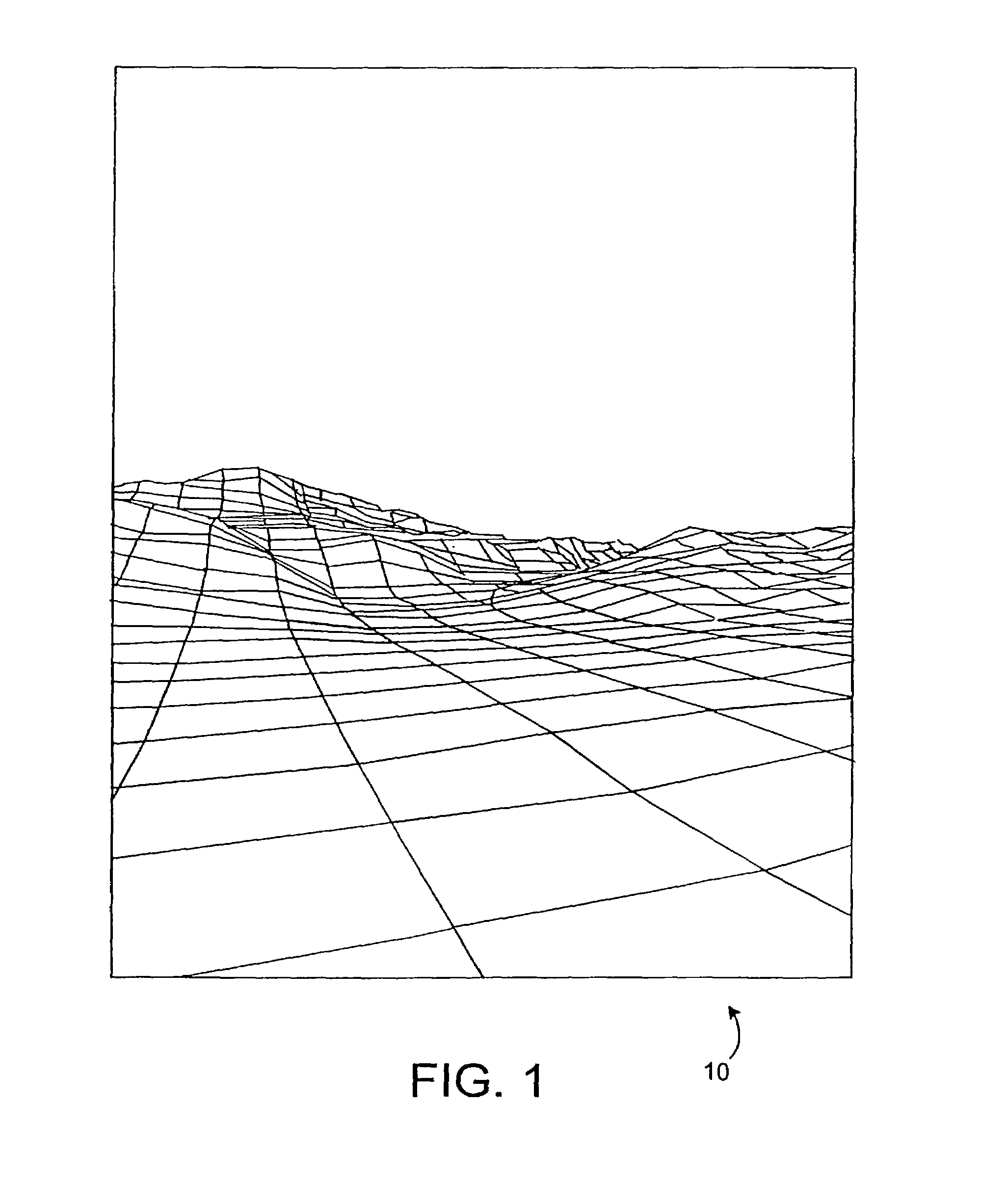
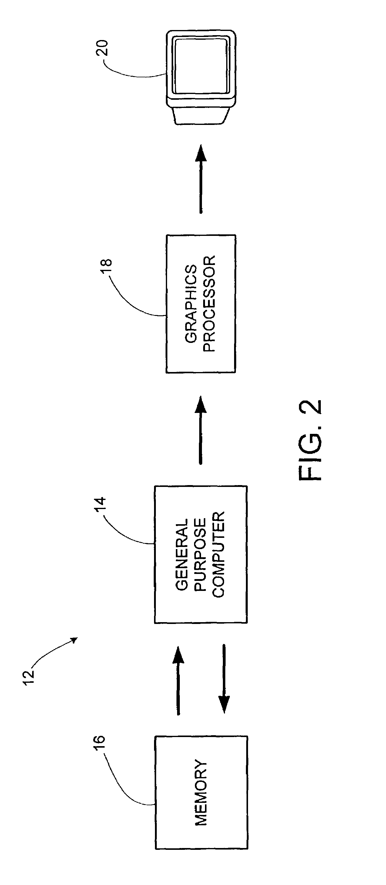
[0015]The present invention provides for the production of a synthetic image of terrain below and in front of an aircraft, e.g., the image 10 shown in FIG. 1. The image produced is adjusted to conform to a selected field of view and to the immediacy of objects of concern. A system 12 for carrying out the method of the present invention is shown schematically in FIG. 2. The system 12 includes a computer 14 (which may be a general purpose computer or a dedicated, specially designed computer), a memory 16 containing raw terrain elevation data, a graphics processor 18 and a display 20. The display 20 may be, for example, a cathode ray tube (CRT), a liquid crystal display screen, a gas plasma-based flat panel display, or other suitable display device.

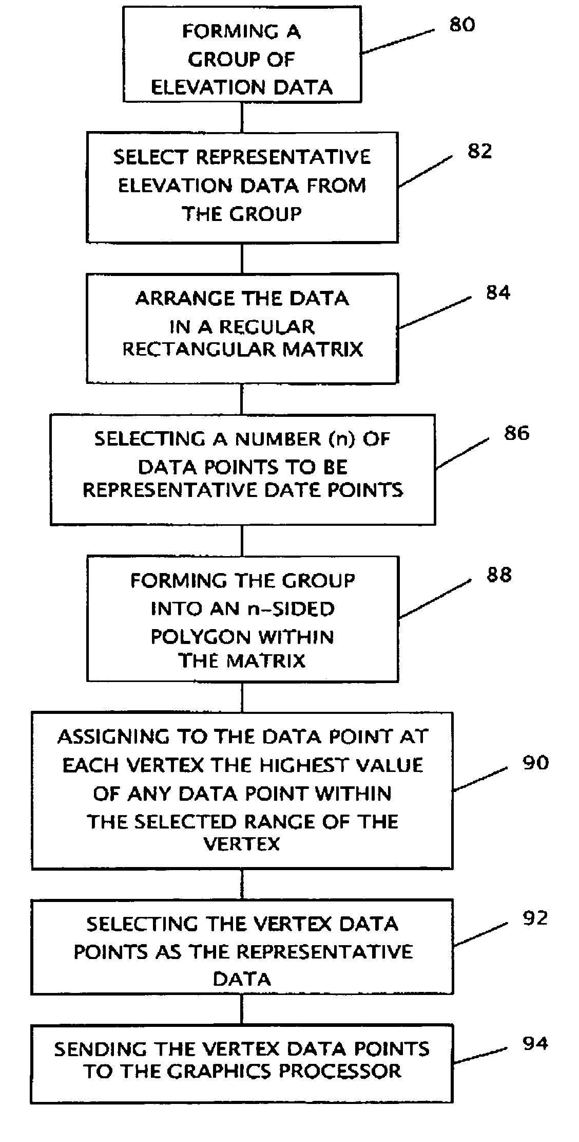
[0016]The process of rendering an image from the raw terrain data takes place in two broad steps. First, a set of tiles representing terrain elevation data for specific geographic regions is created. Then, the set of tiles is addressed and t...


PUM


Abstract

A synthetic rendering of the terrain within a selected field of view is created from raw terrain elevation data, and the resolution of the rendering is proportioned to the altitude above ground level (altitude AGL) of the aircraft. All the data points are subdivided into tiles. Only data from tiles within a prescribed field of view are considered for processing; all others are ignored. Within the selected tiles, only some of the terrain elevation data points are passed to the graphics processor for rendering. At maximum resolution, when the aircraft is on the ground or at a low altitude, there are relatively fewer tiles within the field of view and the fraction of the data points from each tile within the field of view passed for rendering is relatively large. As the aircraft's altitude AGL level increases, the field of view also increases in area increasing the number of tiles within the field of view. However, the number of data points forwarded for rendering by the graphics processor is kept approximately constant by selecting progressively fewer and fewer terrain elevation data points from each tile for rendering as altitude AGL increases. Only the data points that lie within tiles inside a prescribed field of view are forwarded to the graphics processor for rendering. Once the tiles have been selected, the terrain elevation data points are grouped in groups of a size that depends on altitude AGL, with more terrain data points in the grouped as attitude increases. Preferably the groups are triangle strips. Only the highest elevation from each group is passed to the graphics processor for rendering.

Description

[0001]This application claims the benefit of U.S. Provisional Application No. 60 / 303,578 filed Jul. 6, 2001.FIELD OF THE INVENTION[0002]The present invention addresses the problem of presenting an appropriate synthetic image of the terrain below an aircraft to the pilot on a screen such as a CRT or flat panel display.BACKGROUND OF THE INVENTION[0003]Contemporary aircraft make extensive use of computer generated displays. Compared to earlier instrumentation, computer generated displays are easier for pilots to use and to understand; an advantage that can prove important when quick decisions must be made. One portion of such a display could be a synthetic view of the ground below the aircraft. Such a view can be generated from raw terrain data such as the commercially available U.S. Geological Survey Digital Elevation Model data or the Defense Mapping Agency's Digital Terrain Elevation Data.[0004]Raw terrain data is stored in a large table. The table stores information about the eleva...

Claims


Application Information

Patent Timeline
IPC IPC(8): G06T17/00G01C23/00G02B27/00G02B27/01G06T15/10G06T17/05
CPCG01C23/00G02B27/01G06T15/10G06T17/05G02B2027/0138G02B2027/014
Inventor BRUST, CLIFFORD S.
Owner L 3 COMM AVIONICS SYST
Why Eureka
Try Eureka