Electronic endoscope eliminating influence of light distribution in optical zooming

an endoscope and optical zoom technology, applied in the field of electronic endoscopes, can solve the problems of difficult to obtain even brightness and redness, and achieve the effect of improving the redness of an enlarged image in extreme close up photography and reducing the color signal formation circui

Inactive Publication Date: 2006-10-17
FUJI PHOTO OPTICAL CO LTD
View PDF6 Cites 55 Cited by
  • Summary
  • Abstract
  • Description
  • Claims
  • Application Information

AI Technical Summary

Benefits of technology

[0017]According to the third aspect of the invention, when the movable lens is driven, for example, to a Near end, for example, a level of a red (R) color signal obtained via the ...

Problems solved by technology

However, in the electronic endoscope having an optical zoom mechanism, there is a problem that varying light distribution prevents an image with even brightness from being obtained in close up photography for obtaining an enlarged image. FIG. 15 shows a state in which a tip of a scope is brought close to the object to be observed, and as shown in this drawing, there are provided, at a tip of a scope 2 for taking an image of an object to be observed 1, illumination windo...

Method used


Image

  • Electronic endoscope eliminating influence of light distribution in optical zooming
  • Electronic endoscope eliminating influence of light distribution in optical zooming
  • Electronic endoscope eliminating influence of light distribution in optical zooming

Examples


first embodiment

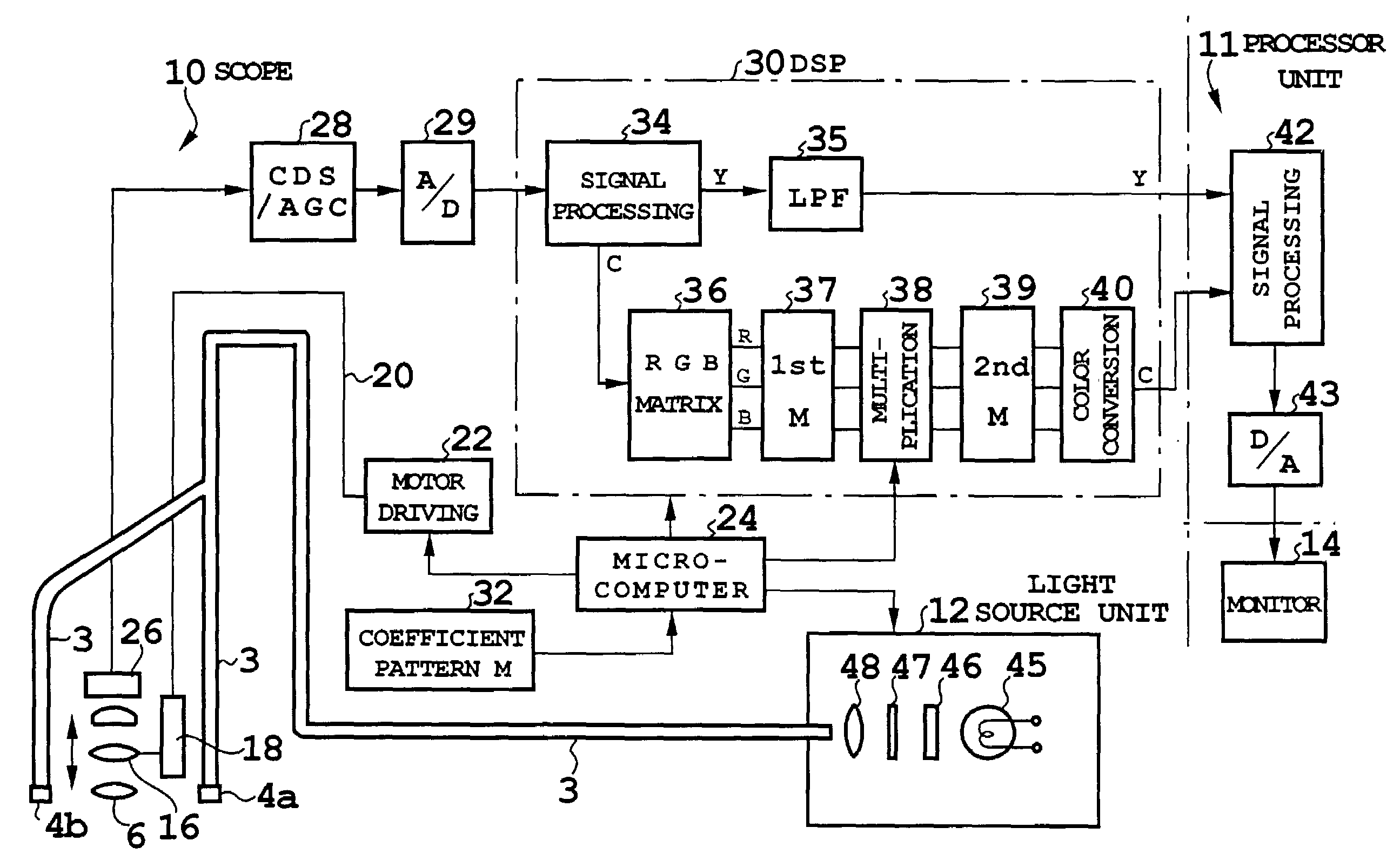
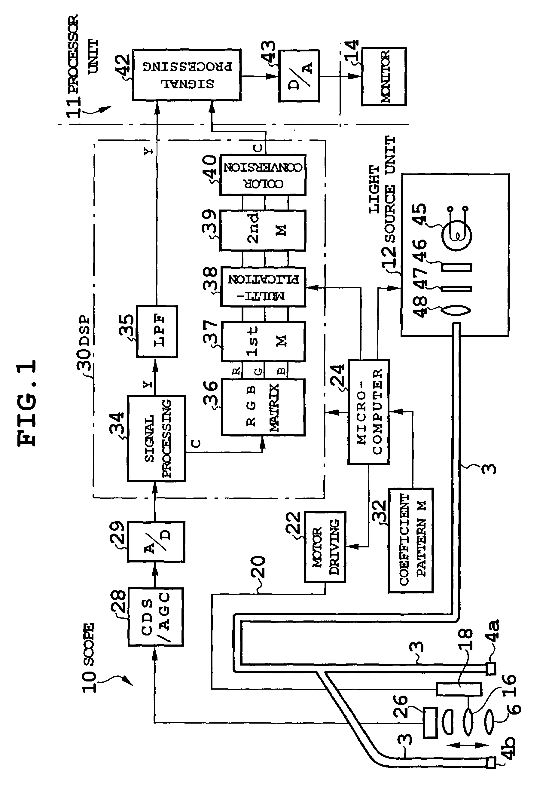
[0035]FIG. 1 shows a configuration of an electronic endoscope according to a first embodiment. The electronic endoscope is of a simultaneous type, and includes a scope 10, a processor unit 11, a light source unit 12, and a monitor 14. The endoscope in FIG. 1 includes, at a tip of the scope 10, illumination windows 4a, 4b and an observation window 6, and a light guide 3 guided from the light source unit 12 connects to the illumination windows 4a, 4b.

[0036]The observation window 6 constitutes an objective optical system, the objective optical system includes a movable lens 16, and the movable lens 16 is held by and connected to a moving mechanism 18. To the moving mechanism 18, a motor driving unit 22 connects via a rotating linear transfer member 20, and the motor driving unit 22 is controlled by a microcomputer 24. Specifically, based on operation of a zoom switch placed at an operating portion or the like of the scope 10, the microcomputer 24 rotates a motor of the motor driving u...

second embodiment

[0050]FIG. 6 shows a configuration of a second embodiment, and in this embodiment, a coefficient for even brightness does not depend on pattern memory, but is calculated in each case. In FIG. 6, in this embodiment, there are provided a coefficient calculation circuit 50 for feeding a coefficient to a multiplier 38, and a microcomputer 51 for controlling the coefficient calculation circuit 50, and the coefficient calculation circuit 50 calculates a coefficient curve (an inversion curve of a light distribution curve) corresponding to a lens position (focusing distance) of a movable lens 18.

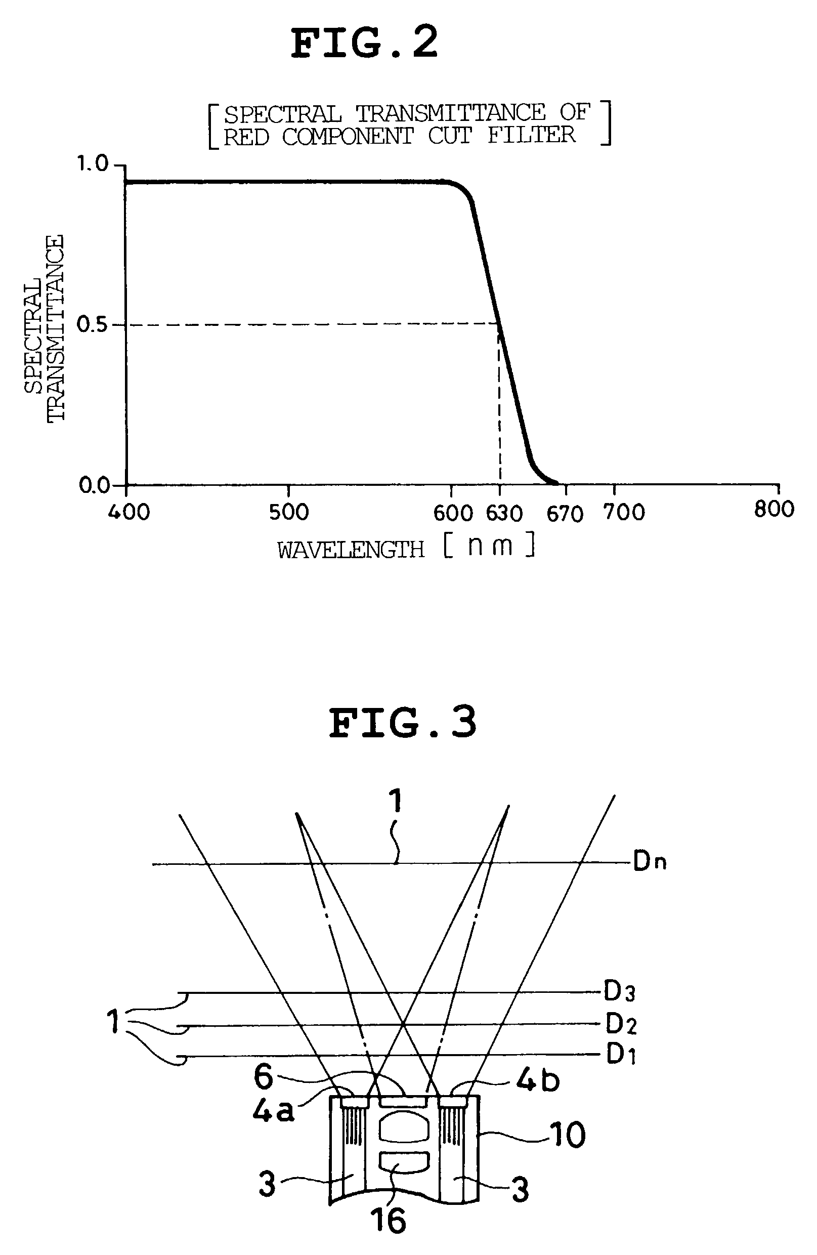
[0051]FIG. 7 shows a light distribution curve and a light illumination state when focusing at a distance D1 in FIG. 3, and the light distribution curve can be obtained by applying an interval d between central positions O1, O2 in illumination areas of lights S1, S2 determined by the focusing distance, and a radius r of the light illumination area, to an arithmetic equation. For example, values of d,...

third embodiment

[0055]FIG. 8 shows a main configuration of an electronic endoscope (scope) according to a third embodiment, and the configuration is similar to the configuration of the first embodiment except for a DSP (digital signal processor) 130 and a microcomputer 124 for controlling the DSP 130. In FIG. 8, the DSP 130 for inputting a video signal from an A / D converter 29 includes a signal processing circuit 132 for performing various kinds of processing such as white balance, or gamma correction, and in the signal processing circuit 132, a Y (brightness) signal and color difference (C) signals of R (red)−Y and B (blue)−Y are formed by color conversion calculation from signals obtained through color filters of Mg, G, Cy, Ye of a CCD 26. There are also provided a line memory 133 for storing the Y signal output from the signal processing circuit 132 for each horizontal line, an averaging circuit 134 for successively determining averages, for example, for 32 pixels (a different number of pixels i...


PUM


Abstract

The invention provides an endoscope having a scope that takes an image enlarged by driving a movable lens of an optical zoom mechanism by a CCD and displays an image of an object to be observed, wherein a multiplier multiplies RGB color signals by a coefficient set in view of light distribution of illumination light depending on focusing distances of the movable lens, thus eliminating uneven brightness resulting from varying light distribution depending on the focusing distances in enlargement photography. A red component cut filter for cutting a long wavelength side in a red band of the illumination light is provided in a light source unit to improve redness. Further, a coefficient for averaging a brightness signal for a predetermined number of pixels for each horizontal line is calculated, and this coefficient calculation may eliminate unevenness.

Description

BACKGROUND OF THE INVENTION[0001]This application claims the priority of Japanese Patent Applications Nos. 2001-299226 and 2001-299227 and 2001-301804 filed on Sep. 28, 2001 which are incorporated herein by reference.[0002]1. Field of the Invention[0003]The present invention relates to an electronic endoscope having an optical zoom mechanism, and more particularly, to image processing by an electronic endoscope in which a movable lens is driven to bring a tip of a scope close to an object to be observed, and to take an enlarged image.[0004]2. Description of the Related Art[0005]An electronic endoscope takes an image, by an image pickup device such as a CCD (Charge Coupled Device), of an object to be observed, captured via an objective optical system by applying illumination light, and displays the image of the object to be observed on a monitor or the like. Recently, in the electronic endoscope of this type, a movable lens (varifocal type) has been incorporated into the objective op...

Claims


Application Information

Patent Timeline
IPC IPC(8): H04N7/18A61B1/04A61B1/05A61B5/00G02B23/24
CPCA61B1/05A61B1/0638A61B5/0059G02B23/2438A61B1/00009
Inventor ABE, KAZUNORIHIGUCHI, MITSURUAYAME, DAISUKETAKEUCHI, SHINJI
Owner FUJI PHOTO OPTICAL CO LTD
Why Eureka
Try Eureka