Data transmitter and data receiver

Inactive Publication Date: 2006-10-17
PANASONIC CORP
View PDF10 Cites 40 Cited by
  • Summary
  • Abstract
  • Description
  • Claims
  • Application Information

AI Technical Summary

Benefits of technology

[0011]The present invention is intended to obviate the above problem of the prior art, and it aims at providing a data transmitt

Problems solved by technology

However, both of the above-described data transmitter and the data recording device have a problem that they need to carry a large mass of hardware, as they require the P

Method used


Image

  • Data transmitter and data receiver
  • Data transmitter and data receiver
  • Data transmitter and data receiver

Examples


Example

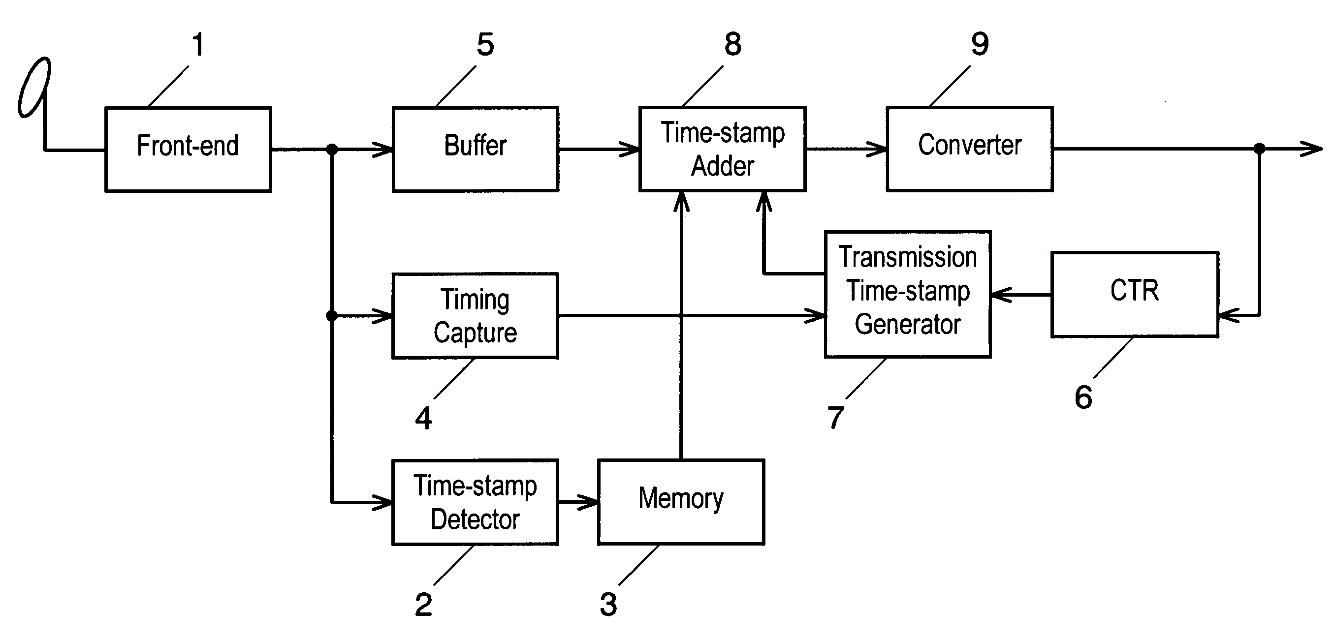
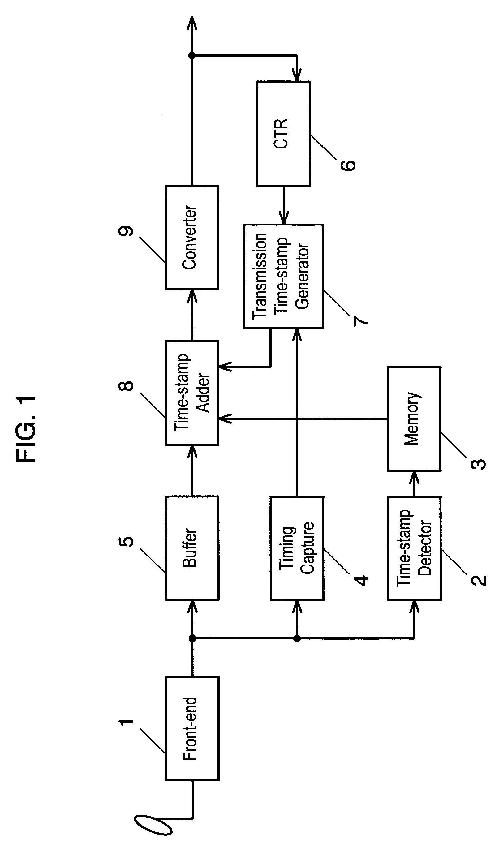
[0023]First, a data transmitter of an exemplary embodiment of the present invention will be described with reference to FIG. 1. The data transmitter shown in FIG. 1 comprises the following blocks:[0024]a front end 1 for executing such processes as demodulation, error correction, and decoding of satellite waves received through an antenna, and outputting a transport stream;[0025]a time stamp detector 2 for detecting in the transport stream a reference time stamp for use in harmonizing a time reference (absolute time represented by a counted value of 27 MHz) between a broadcasting station and a receiver, and a program ID that identifies a program;[0026]a memory 3 for storing the reference time stamp and the program ID detected by the time stamp detector 2;[0027]a reception-timing capture unit 4 for detecting a time, at which a data packet of the transport stream comes in;[0028]a buffer 5 for controlling transmission timing;[0029]a cycle time register (“CTR”) 6 having a counter that co...


PUM


Abstract

A data transmitter for detecting a reference time stamp for use in reproducing a system clock from a transport packet data of a first transport stream, adding the detected reference time stamp as a header information to the transport packet data, converting the transport packet data and the header information into a second transport stream, and transmitting the second transport stream.

Description

FIELD OF THE INVENTION[0001]The present invention relates to a transmitter and a receiver for communicating digital signal of a transport stream in a digital broadcast.BACKGROUND OF THE INVENTION[0002]Digital satellite broadcast first begun in the United States in 1994 has entered into a practical stage for actual use after it has propagated to Japan, European nations, and the other countries in 1996. At the same time, there has been advancement in development of high-speed digital interfaces for receiving such digital signals via digital broadcasting, and transferring them isochronously (in real time) to individual receivers. In particular, a serial bus of the IEEE 1394 standard is expected to be the interface suitable for multimedia transmissions dominated primarily by moving video images, for the reason of such advantages as a high data rate and its ability to carry isochronous transmission and asynchronous transmission simultaneously.[0003]Described hereinafter pertains to a tra...

Claims


Application Information

Patent Timeline
IPC IPC(8): H04J3/06H04L7/04H04L12/70H04N7/24H04N7/62H04N21/236H04N21/43H04N21/434H04N21/4363
CPCH04J3/0632H04N21/23608H04N21/4305H04N21/4344H04N21/43632
Inventor GOTO, SHOICHIMIZOBATA, NORIHIKOIITSUKA, HIROYUKIYAMADA, MASAZUMIYANAGISAWA, RYOGO
Owner PANASONIC CORP
Why Eureka
Try Eureka