Optical amplifier and optical amplification method

a technology which is applied in the field of optical amplifier and optical amplifier, can solve the problems of unintended tilt, inability to tell whether the change in the gain of the optical amplifier is caused, and fluctuation of the loss of optical components,

Active Publication Date: 2006-10-17
FUJITSU LTD
View PDF15 Cites 21 Cited by
  • Summary
  • Abstract
  • Description
  • Claims
  • Application Information

AI Technical Summary

Benefits of technology

[0020]It is an object of the present invention to at l

Problems solved by technology

Since unintended tilt can be a cause of deterioration of a transmission quality, particularly in a long-distance WDM-transmission system, it is necessary to perform gain control to make the tilt flat by an optical amplifier, to transmit all wavelengths with equivalent qualities.
The optical component loss fluctuates (in general, increases) due to aged deterioration and failure of the optical components, vibration impact at the time of transportation, a wind pressure due to forced air cooling, occurrence of a bending loss in a winding portion of an optical fiber due to a change in temperature, and the like.
Therefore, when changes, it is impossible to tell whether the chan

Method used


Image

  • Optical amplifier and optical amplification method
  • Optical amplifier and optical amplification method
  • Optical amplifier and optical amplification method

Examples


first embodiment

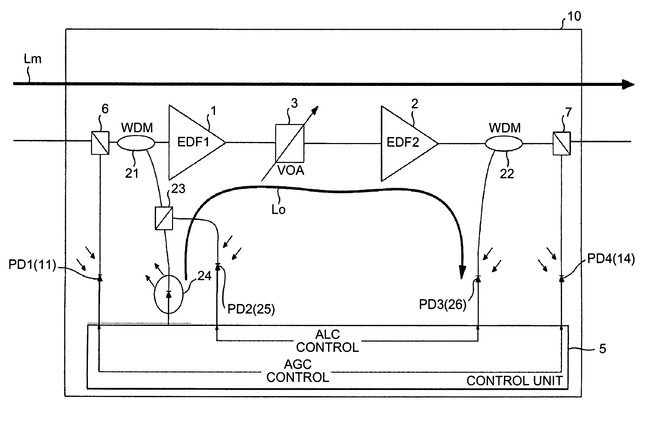
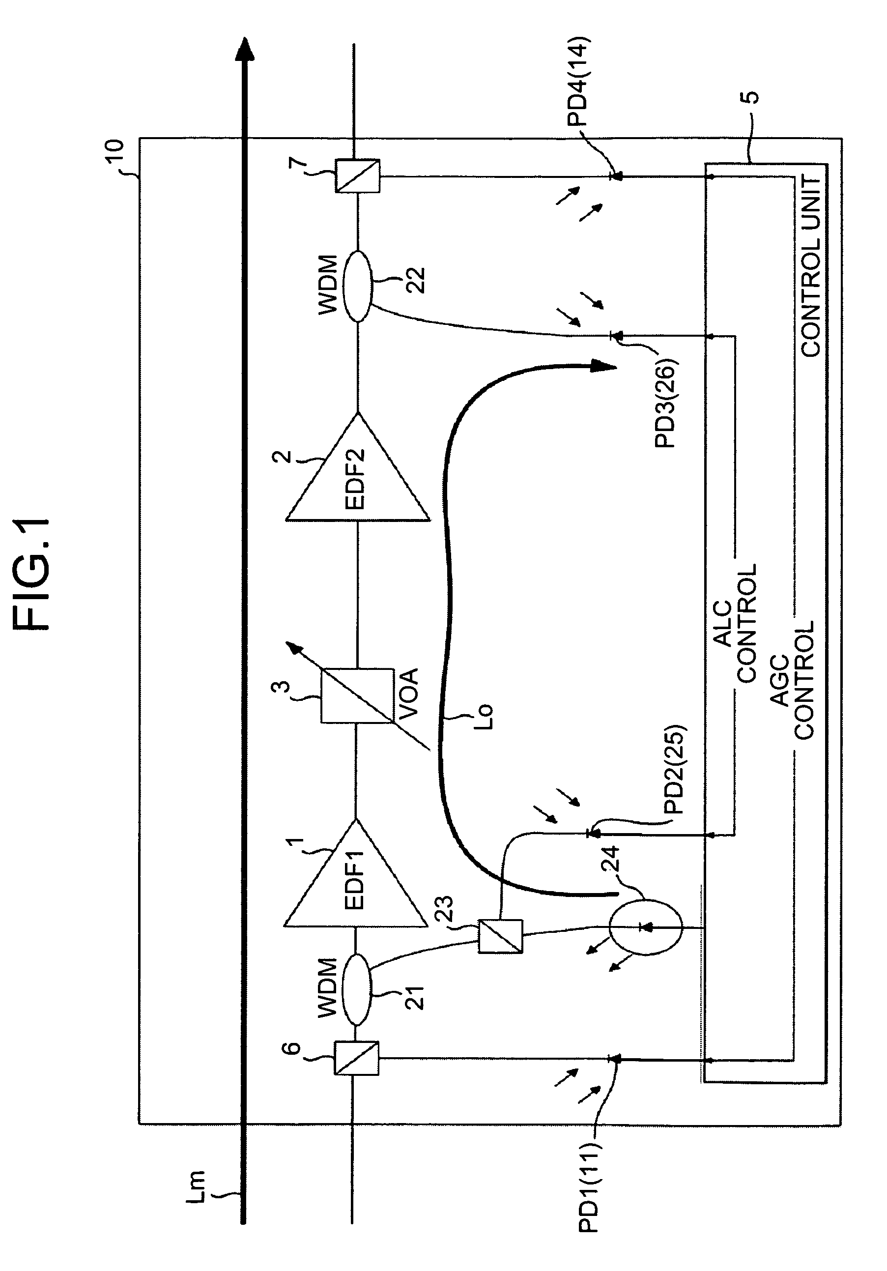
[0049]FIG. 1 is a schematic of an optical amplifier according to the present invention. An optical amplifier 10 includes EDFs (an EDF 1 and an EDF 2) 1 and 2 arranged in two stages and a variable optical attenuator (VOA) 3 provided between the EDFs 1 and 2. The optical amplifier 10 performs control to make output power constant even if input power of a main signal (a light signal) Lm of a WDM on a transmission path fluctuates.

[0050]In the EDFs 1 and 2, when intensity of excitation light is changed and a gain changes as described above, tilt changes. Thus, a control unit 5 performs AGC to make gains of the EDFs 1 and 2 constant. When input power of input of the light signal Lm to the EDF 1 changes, the control unit 5 performs ALC for keeping output power of the EDF 2 constant by adjusting an attenuation amount of the VOA 3 while making a gain of the EDF 1 constant.

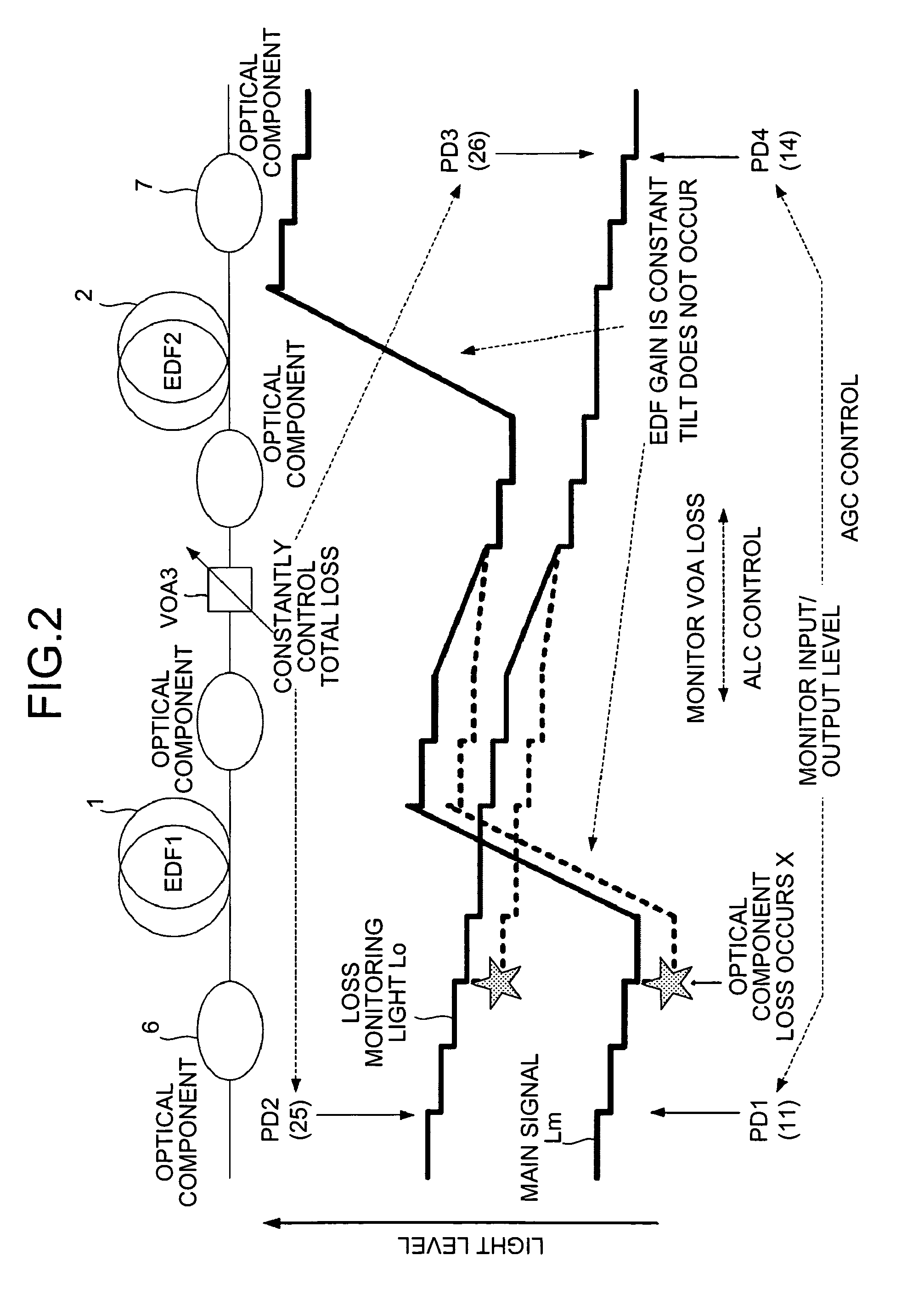
[0051]Plural optical components are arranged on a path of the light signal Lm in the inside of the optical amplifier 10. ...

second embodiment

[0095] it is possible to supply the loss monitoring light Lo from a single device to plural devices such as a repeater provided on the transmission path. This makes it unnecessary to provide a light source of the loss monitoring light Lo (the LD for monitoring light 24 shown in FIG. 1) for each of the devices. Thus, it is possible to perform control for compensating for a loss in each of the devices independently while simplifying a configuration of the device and reducing cost of the device.

[0096]The loss monitoring light Lo in the configuration described above attenuates as the loss monitoring light Lo propagates through the transmission path. The loss monitoring light Lo also attenuates in the devices (the multiplexing station 41, the repeating station 42, and the demultiplexing station 43 shown in FIG. 7). Therefore, a transmission distance of the loss monitoring light Lo according to the second embodiment depends on sensitivity of the PDs 2 and 3 (25 and 26) that detect the los...

third embodiment

[0105]In the present invention, when a plurality of optical amplifiers are provided in one station, a downstream optical amplification unit, which has generated an alarm, requests an upstream optical amplification unit to control output power and the like.

[0106]When a loss of a certain optical amplifier increases and the optical amplifier generates an alarm, if it is possible to increase an input level to the optical amplifier that has generated the alarm, a margin for an amount of attenuation by a VOA is generated because of the increased input level. Thus, it is possible to prevent occurrence of tilt (see, for example, FIG. 21).

[0107]A function for notifying an optical amplification unit provided upstream of a state of generation of the alarm and an amount of increase in a necessary input level is provided in the optical amplification unit that has generated the alarm. The control unit 5 (see FIG. 1) has the function. The optical amplification unit, which receives the notice of ge...


PUM


Abstract

An optical amplifier includes an output unit that outputs a loss monitoring light having a wavelength that causes neither absorption nor gain with respect to each of the wavelengths of a light signal to be amplified with EDFs; a multiplexing unit that multiplexes the loss monitoring light with the light signal at an input stage of the light signal; a demultiplexing unit that demultiplexes the loss monitoring light from multiplexed light signal at an output stage of the light signal; a detecting unit that detects intensity of loss monitoring light at the input stage and intensity of loss monitoring light at the output stage; a calculating unit that calculates, based on the intensities, a loss of the loss monitoring light that has occurred between the input stage and the output stage; and a control unit that controls, based on the loss, the variable optical attenuator.

Description

CROSS-REFERENCE TO RELATED APPLICATIONS[0001]This application is based upon and claims the benefit of priority from the prior Japanese Patent Application No. 2005-282822, filed on Sep. 28, 2005, the entire contents of which are incorporated herein by reference.BACKGROUND OF THE INVENTION[0002]1. Field of the Invention[0003]The present invention relates to a technology for amplifying light of multiple wavelengths in a wavelength division multiplexing (WDM) transmission system.[0004]2. Description of the Related Art[0005]A WDM optical transmission system can remarkably improve a signal transmission capacity by collectively amplifying a plurality of wavelengths using an optical amplifier. An optical amplifier most frequently used is an optical fiber amplifier doped with a rare earth element such as erbium.[0006]Such an optical fiber doped with erbium (herein after, “erbium doped fiber (EDF)”) amplifies signal lights in a range of 1.53 micrometers (μm) to 1.6 μm with excitation light in...

Claims


Application Information

Patent Timeline
IPC IPC(8): H01S3/13H01S3/067H01S3/10H04B10/07H04B10/077H04B10/079H04B10/29H04B10/294H04J14/00H04J14/02
CPCH04B10/0771H04B10/296H04B2210/003
Inventor MORI, SHOTAHIRAIZUMI, MAKI
Owner FUJITSU LTD
Why Eureka
Try Eureka