Database synchronization apparatus in element management system and method therefor

a database and element management technology, applied in the field of element management system, can solve the problems of long initialization process of synchronization between the ems and each ne, difficult to apply real-time data, inaccurate and rapid application of modified db generated between the ems and the nes, etc., to achieve the effect of real-time db monitoring and managemen

Inactive Publication Date: 2006-10-17
ERICSSON-LG
View PDF20 Cites 35 Cited by
  • Summary
  • Abstract
  • Description
  • Claims
  • Application Information

AI Technical Summary

Benefits of technology

[0011]Accordingly, it is an object of the present invention to provide a method for synchronization between an EMS and a NE which facilitates a real-time DB monitoring and management by transmitting the status information of a modified NE.

Problems solved by technology

However, the former method has a disadvantage that since the EMS demands that each NE reports its modified DB by item and by pattern, the initialization process for synchronization between the EMS and each NE is lengthened.
Accordingly, there arises a problem that it is difficult to apply the modified DB generated between the EMS and the NEs to the EMS accurately and rapidly.
On the contrary, when the reporting period is lengthened, the amount of sync-related data is increased, making it difficult to apply a real-time data.

Method used


Image

  • Database synchronization apparatus in element management system and method therefor
  • Database synchronization apparatus in element management system and method therefor
  • Database synchronization apparatus in element management system and method therefor

Examples


Embodiment Construction

[0023]Preferred embodiments of the present invention will now be described with reference to the accompanying drawings.

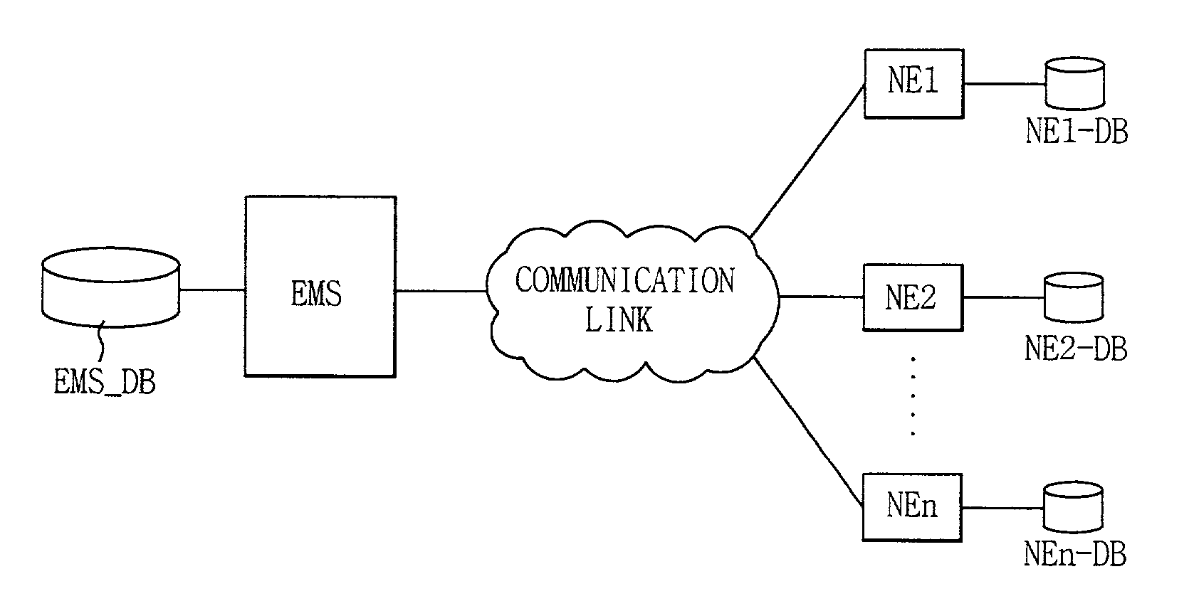
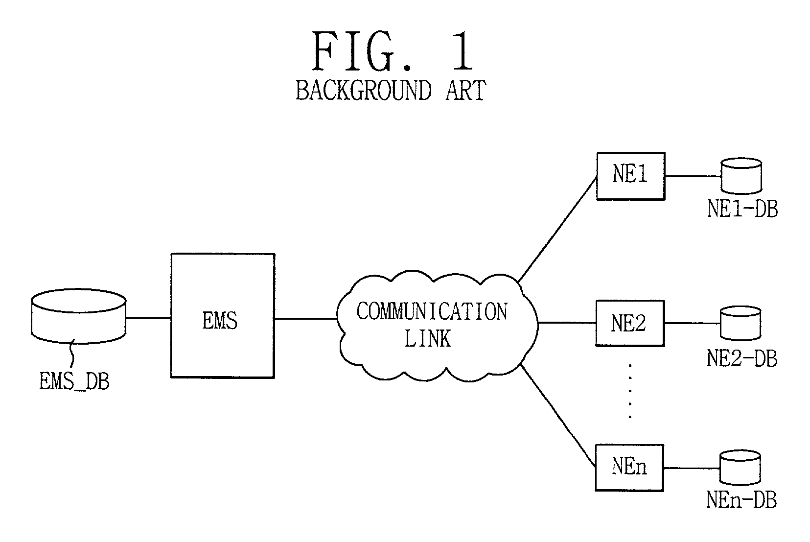
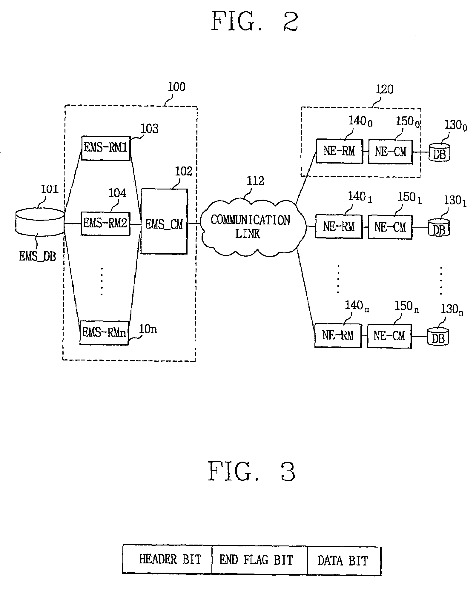
[0024]FIG. 2 is a block diagram of a communication network of a WDCS_EMS and WDCS_NEs according to the present invention and, in particular, a block diagram of a communication network of a EMS and NEs in a transmission network of a plurality of wide distribution control system network elements (hereinafter referred to as NE) 120˜12n and a wide distribution control system element management system (hereinafter referred to as EMS) 100 which operates and manages NEs. A EMS and a N number of NEs are connected through a communication link 112 of the same pattern as a packet network.

[0025]Each of the NEs is comprised of the same DB 1300–130n as the conventional methods, a common memory (hereinafter referred to as NE_CM) 1500–150n in which DB information and alarm state information are rearranged, and a sync-related memory (hereinafter referred to as NE_RM) 1400–140n which...


PUM


Abstract

The present disclosure relates to a database (DB) synchronization apparatus of a transmission network system which includes a plurality of network elements (NEs) and an Element Management System (EMS). Each of the NEs may include a common memory in which DB information and alarm state information are rearranged and a sync-related memory of the same pattern as the common memory for maintaining DB identity with the EMS. The EMS may include a EMS sync-related memory for storing the DB and the information of the sync-related memory of the plurality of NEs, and a EMS common memory corresponding to the common memory (CM) of the NE. A common memory which reflects database information and the current alarm information to the NEs, and a sync-related memory which stores data prior to a T-second period are built on the NEs, and these two memories are compared in block units to thereafter transmit only modified block data to the EMS. Accordingly, there is the advantage that since synchronization is established by the comparison of the memories, an initialization execution time is very fast, and a real-time data monitoring and management is convenient.

Description

BACKGROUND OF THE INVENTION[0001]1. Field of the Invention[0002]The present invention relates to an EMS(Element Management System) and, in particular, to a method for a database synchronization between an EMS and NEs(Network Elements).[0003]2. Description of the Prior Art[0004]Generally, in a transmission network system, since a network element management system processes real-time data, a status of a network element (hereinafter referred to as NE) must be analyzed accurately and rapidly for thereby reporting to the network element management system.[0005]FIG. 1 is a view illustrating a network EMS(hereinafter referred to as EMS) and network elements in the conventional art.[0006]As shown in FIG. 1, each of the NEs has its NE_DataBase(hereinafter referred to as NE_DB). In the case that a data such as a DB, DB information, alarm state information, etc. is modified, the NE reports its changed status to the EMS, and the EMS performs a network management using a newly reported data.[000...

Claims


Application Information

Patent Timeline
Patent Type & Authority Patents(United States)
IPC IPC(8): G06F12/00H04L12/24H04L29/08
CPCH04L41/024H04L67/1095Y10S707/99953
Inventor CHOI, JOONG-KYU
Owner ERICSSON-LG
Why Eureka
Try Eureka