Method and apparatus for reducing air consumption in gas conditioning applications

Inactive Publication Date: 2006-10-24
SPRAYING SYST
View PDF14 Cites 6 Cited by
  • Summary
  • Abstract
  • Description
  • Claims
  • Application Information

AI Technical Summary

Benefits of technology

[0008]It is a further object of the invention to provide a method and system for producing greater efficiency in gas conditioning applications.
[0009]This invention reduces air consumption of spray nozzles of the type used in gas cooling applications. In particular, these nozzles receive both a pressurized air supply as well as a liquid. The flow rates and pressures of the

Problems solved by technology

This results in increased air consumption and in increased compressed air energy cost.
For maintaining the cooling re

Method used


Image

  • Method and apparatus for reducing air consumption in gas conditioning applications
  • Method and apparatus for reducing air consumption in gas conditioning applications
  • Method and apparatus for reducing air consumption in gas conditioning applications

Examples


Example

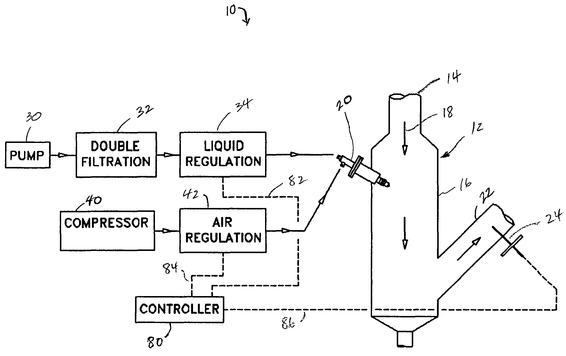
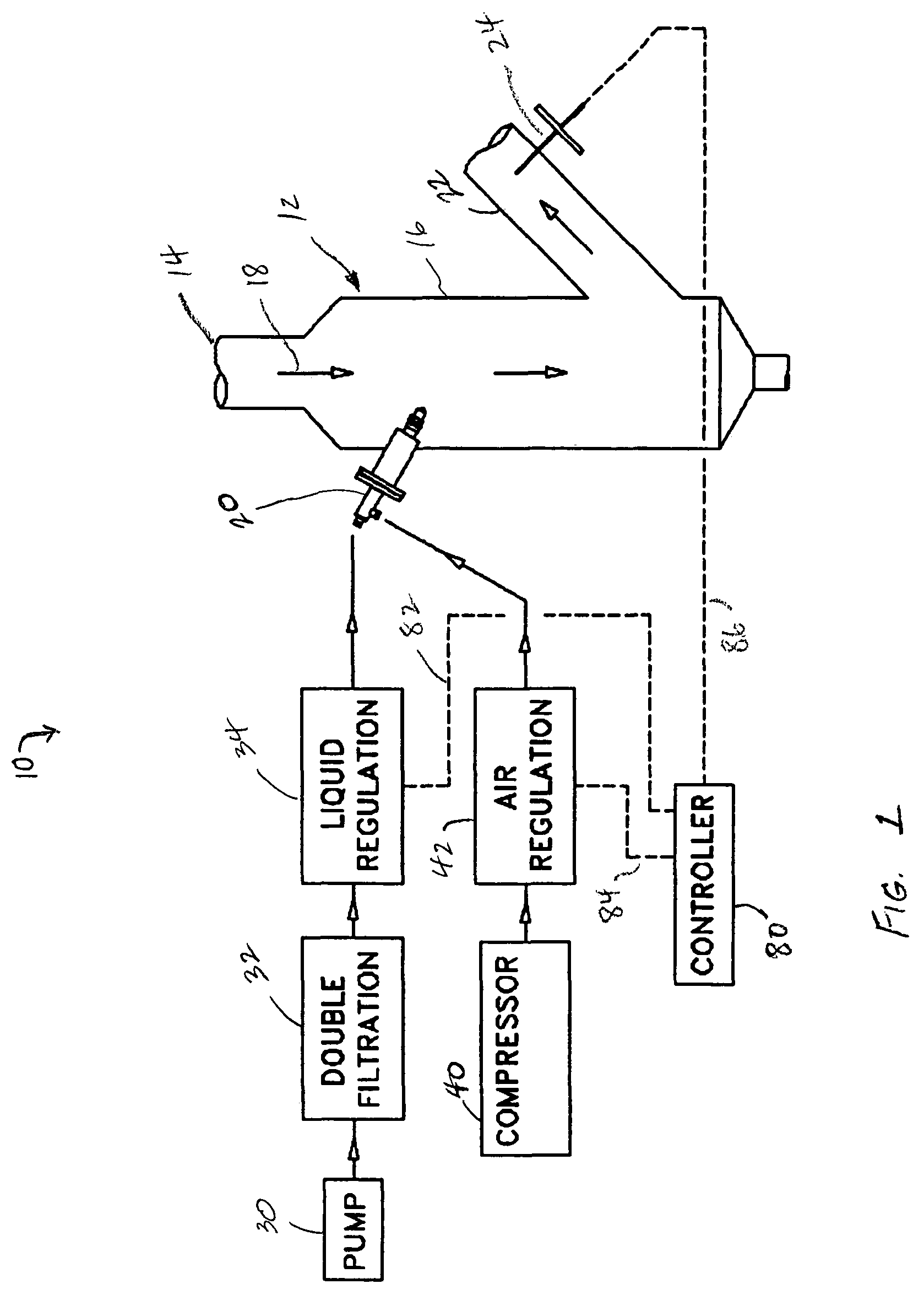
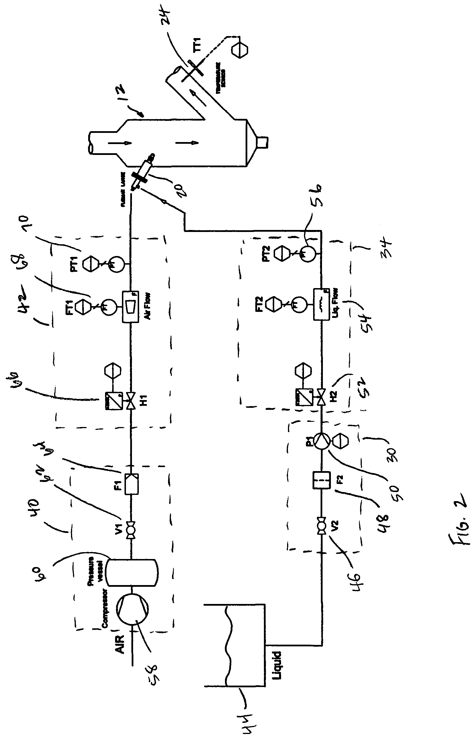
[0014]The present invention generally relates to a control system that monitors various operating parameters of a spray control system for gas conditioning applications. The control system monitors the flow rate of liquid passing through a spray nozzle. The system then processes the detected flow. In response, the system provides a signal indicative of air pressure supplied to the nozzle. This achieves a reduction of the compressed air consumption and an energy savings of compressed air generation.

[0015]This invention has particular applicability to various industrial areas. These include the pulp and paper industry, waste recycling, steel fabrication, environmental control and power generation. Various applications within these general areas include flue gas cooling prior to dust collection processing stages such as bag-house dust collection devices. In addition, the invention may be employed in conjunction with nitrous oxide control such as in fossil fuel consumption and for diese...


PUM

PropertyMeasurementUnit
Lengthaaaaaaaaaa
Lengthaaaaaaaaaa
Lengthaaaaaaaaaa

Abstract

A control system for adjusting the desired air pressure provided to one or more spray nozzles disposed to receive liquid and compressed air adjusts the amount of compressed air supplied to the spray nozzle based on various sensed operating parameters of the system.

Description

FIELD OF THE INVENTION[0001]This invention generally relates to spray control systems and more particularly, to spray control systems used to monitor operating conditions in industrial gas conditioning applications and for compensating for changes in the system to optimize consumed compressed air by the system.BACKGROUND OF THE INVENTION[0002]Industrial production plants often generate hot or flue gases. Such flue gases must usually be cooled for proper operation of the production plant. In these applications, the flue gases are often passed through various portions of the production plant to provide a cooling effect. In other cases, however, additional cooling and conditioning systems must be utilized to produce the proper temperature. The flue gas is sometimes cooled by injecting an atomized liquid stream into the gas stream, such as through spraying water with very fine droplets into the gas stream. This operates to reduce the temperature of the gas stream.[0003]There are typical...

Claims


Application Information

Patent Timeline
IPC IPC(8): B01F3/04B05B7/04B05B7/24B05B7/26B05B12/00B05B12/08B05B12/12B05B15/02F23J15/06F27D17/00
CPCB05B7/2489B05B12/004B05B12/085B05B12/12B05B15/02Y10S261/09B05B12/006B05B15/50
Inventor WULTEPUTTE, LIEVEN
Owner SPRAYING SYST
Why Eureka
Try Eureka