Method of making resilient structure including inserting heated coil spring through side surface of fiber batt

Inactive Publication Date: 2006-10-24
L & P PROPERTY MANAGEMENT CO
View PDF33 Cites 6 Cited by
  • Summary
  • Abstract
  • Description
  • Claims
  • Application Information

AI Technical Summary

Benefits of technology

[0014]The present invention provides an improved, more durable and higher quality resilient structure comprised of coil springs located inside a fiber batt. With the resilient structure of the present invention, the coil springs are disposed in the fiber batt with a minimal amount of melt impact to the fiber strands in the fiber batt. Further, the resilient structure of the present invention has fiber strands interlayered with the turns of the coil spring. Thus

Problems solved by technology

If the fiber density is too high, the seat cushion or mattress will have sufficient rigidity but it will be too firm.
However, it will not be as durable and will be more susceptible to flattening out after use.
Thus, while fiber batting has a number of well-recognized advantages, it is difficult to achieve a high degree of structural support and/or comfort for a resilient structure with a covering or core made from a heat bonded low melt fiber batt.
While a resilient structure with an interconnected wire lattice of this type has many desirable features, it requires a relatively large quantity of steel.
Moreover, its manufacture and construction also requires relatively complex machinery to form and interconnect the steel.
The overall cost of a typical resilient mattress of this type reflects the relatively high quantity of steel used to make the support lattice and the complexity of the required machinery.
That process diminishes the integrity of the fiber batt at the location of the tear, and further, any fiber strand tearing prohibits the coil spring from interlocking with its i

Method used


Image

  • Method of making resilient structure including inserting heated coil spring through side surface of fiber batt
  • Method of making resilient structure including inserting heated coil spring through side surface of fiber batt
  • Method of making resilient structure including inserting heated coil spring through side surface of fiber batt

Examples


Embodiment Construction

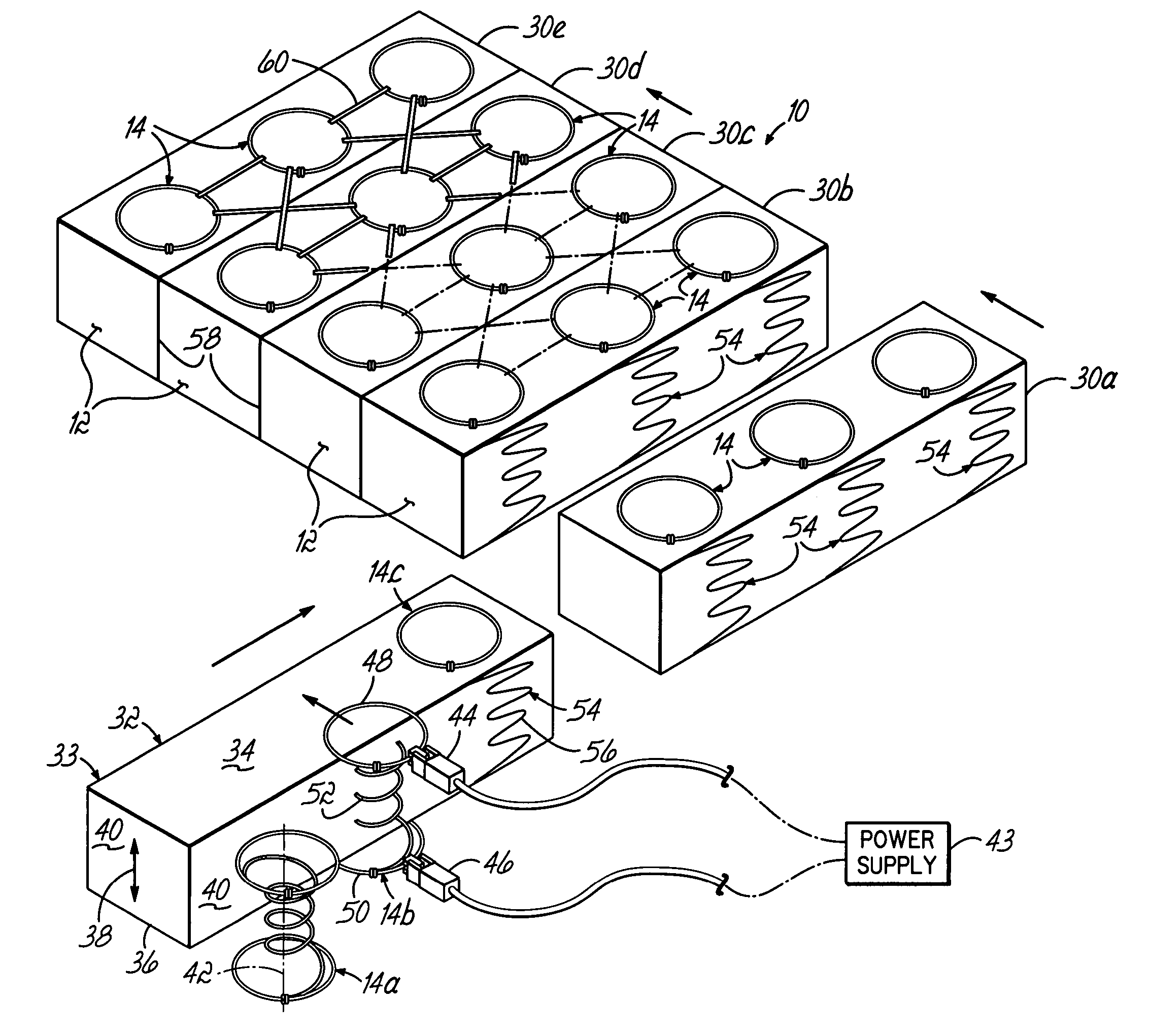
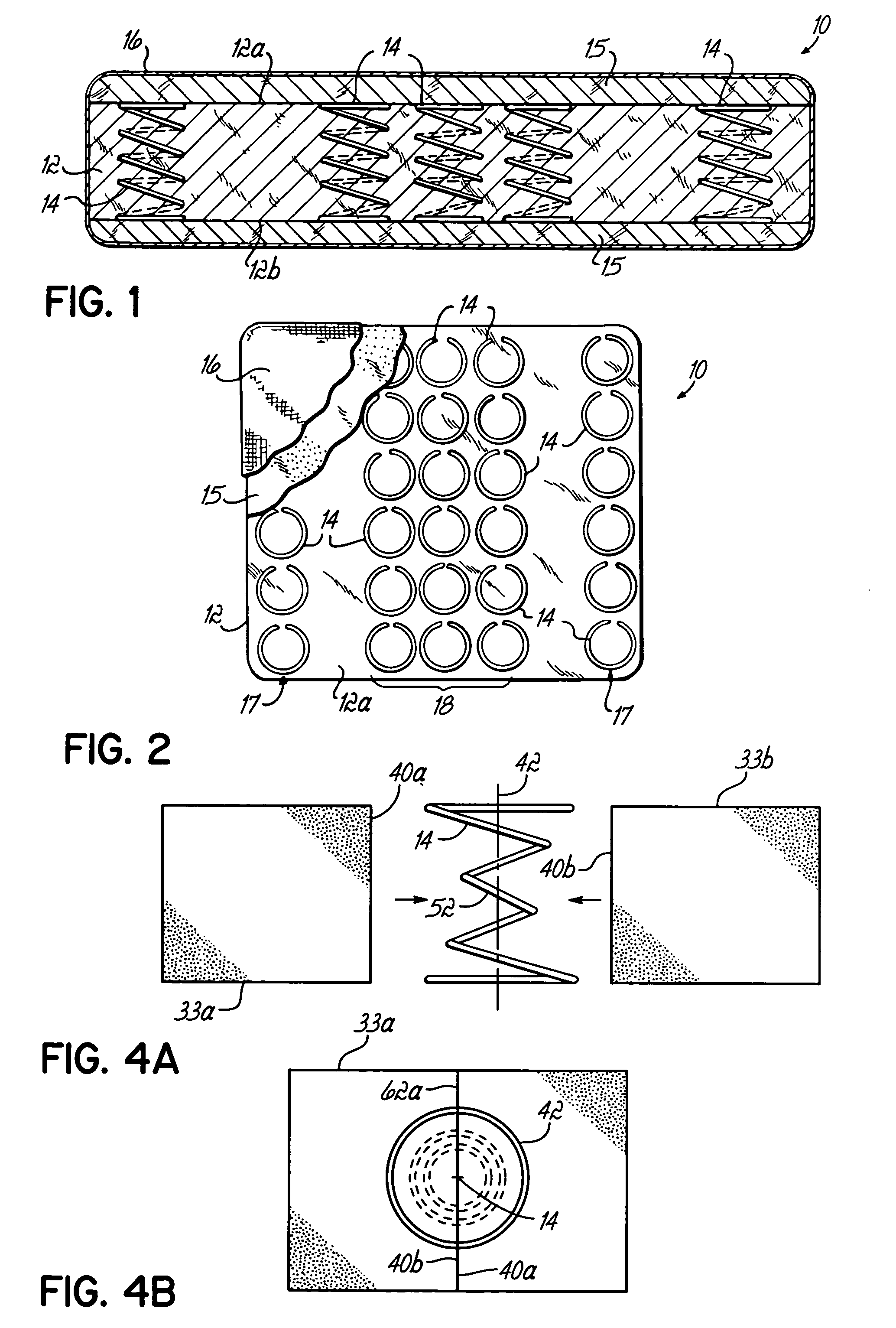
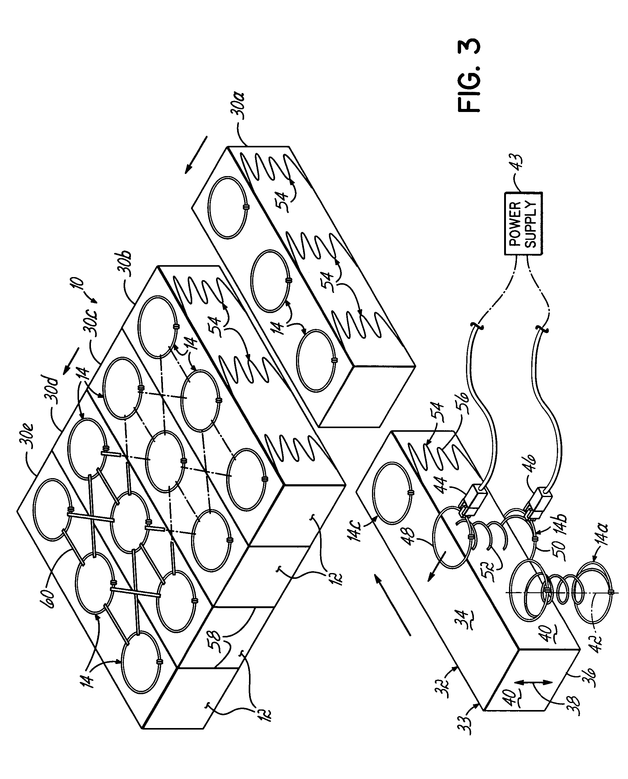
[0035]Referring to FIG. 1, a resilient structure 10 includes a heat bonded, low melt, fiber batt 12. Such a fiber batt may be formed from a bale of dual polymer fibers, for example, Celbond® staple fibers, manufactured by Hoechst Celanese Corporation. The high melt or heat stable fibers are mixed with low melt fibers. Typically, a bale of the dual polymer fibers is picked and fluffed to a desired degree, then tumbled and fed to a feed hopper where it is blended with a desired mixture of heat stable fibers. Thereafter, the fiber mass is carded by a series of garneting machines and layered until a desired weight is achieved, as is known in the industry.

[0036]Densifying a fiber batt of this type involves various stages of heating and compressing to form a predetermined thickness. The dual polymer fiber includes a low melt polymer sheath which surrounds a thermally stable polyester core. When heated, compressed and allowed to cure, the external sheaths randomly adhere to surrounding fib...


PUM

PropertyMeasurementUnit
Lengthaaaaaaaaaa
Resilienceaaaaaaaaaa

Abstract

A resilient structure having a fiber batt with coil springs disposed therein and respective coil spring paths. Each of the coil spring paths extending from a respective coil spring and having a profile similar to a cross-sectional profile of the respective coil spring taken in a plane parallel to a length of the coil spring. A method is also provided for heating the coil springs and inserting the coil springs into a side wall of the fiber batt to produce the coil spring paths that have a profile similar to a cross-sectional profile of the respective coil spring taken in a plane parallel to a length of the coil spring.

Description

[0001]This application is a Divisional of U.S. Ser. No. 10 / 127,004, filed on Apr. 19, 2002, now U.S. Pat. No. 6,694,554 which claims the benefit of Provisional Application Ser. No. 60 / 285,585, filed on Apr. 20, 2001, all of which are hereby expressly incorporated by reference herein.FIELD OF THE INVENTION[0002]This invention relates to a resilient structure such as a seat cushion, furniture back or mattress. More particularly, this invention relates to a resilient structure comprising a fiber batt having enhanced resilience and / or support in strategic areas.BACKGROUND OF THE INVENTION[0003]Non-woven fiber batt has a demonstrated usefulness in a wide variety of applications. This material has been used in manufacturing scouring pads, filters, and the like, but is particularly useful as a filler material in various personal comfort items such as stuffing in furniture, mattresses and pillows, and as a filler and insulation in comforters and other coverings. One of the inherent characte...

Claims


Application Information

Patent Timeline
IPC IPC(8): B29C65/02B29C65/44A47C23/053A47C27/05A47C27/06A47C27/20
CPCA47C23/05A47C27/053A47C27/06A47C27/148A47C27/20A47C27/15Y10T156/1002Y10T29/481Y10T156/1079Y10T156/1056
Inventor BULLARD, LARRY I.
Owner L & P PROPERTY MANAGEMENT CO
Why Eureka
Try Eureka