
Casting of non-ferrous metals

Inactive Publication Date: 2006-10-24
ARCONIC TECH LLC
View PDF20 Cites 28 Cited by
  • Summary
  • Abstract
  • Description
  • Claims
  • Application Information

AI Technical Summary

Benefits of technology

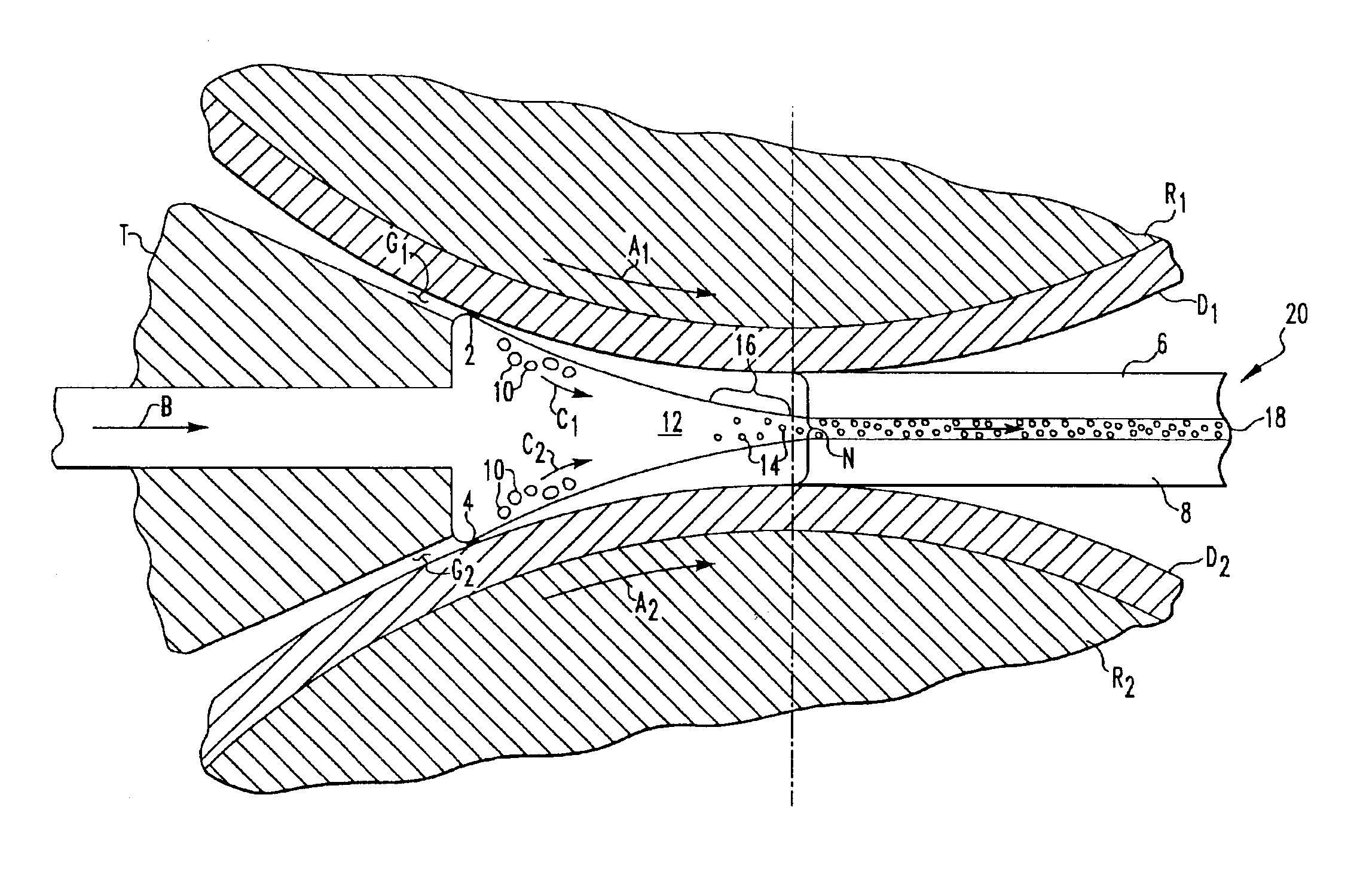
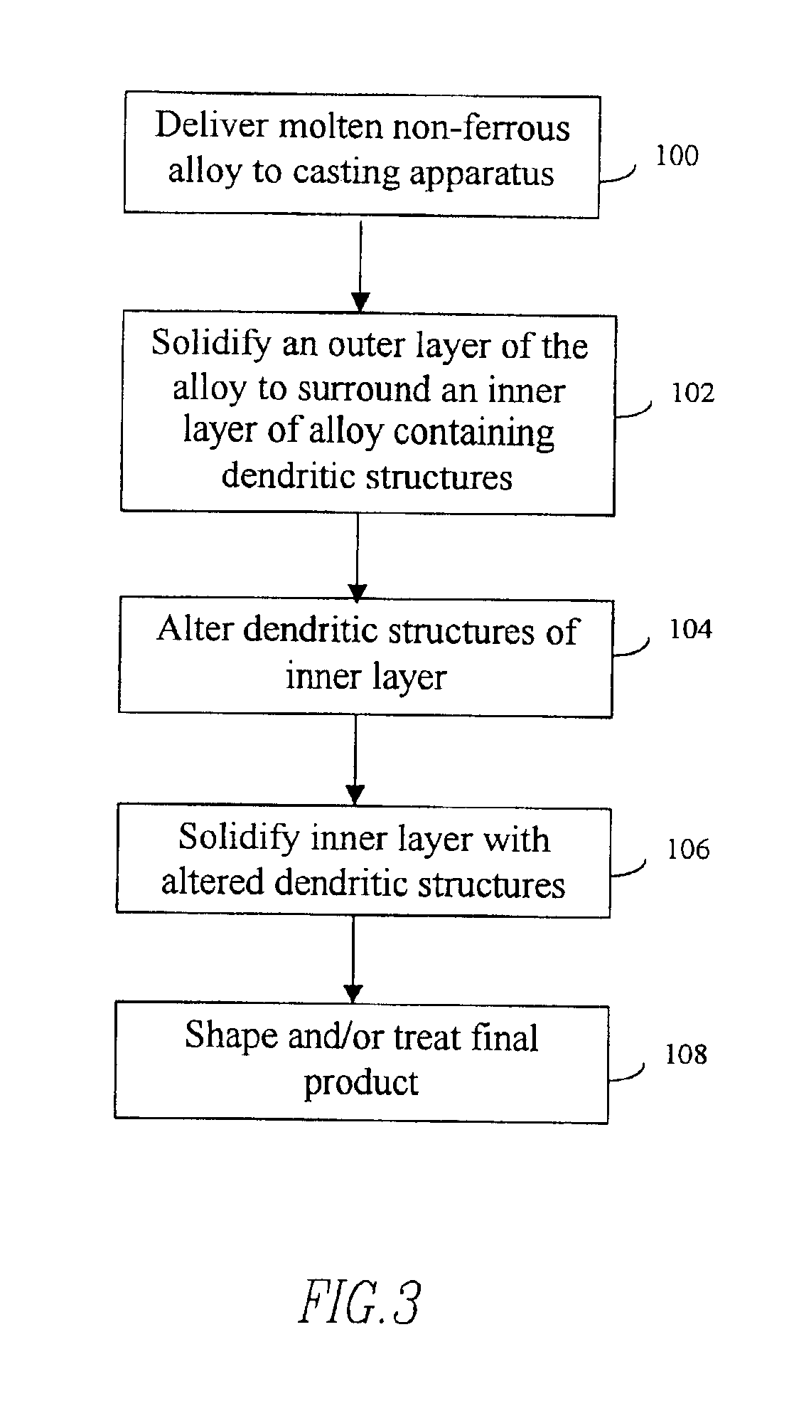
[0024]This need is met by the method of the present invention of casting non-ferrous alloys which includes delivering molten non-ferrous alloy to a pair of spaced apart casting surfaces and rapidly cooling at least a portion of the non-ferrous alloy at a rate of at least about 100° C. per minute thereby solidifying an outer layer of the non-ferrous alloy surrounding an inner layer of a molten component and a solid component of dendrites. Suitable alloys include alloys of aluminum, alloys of magnesium, and alloys of titanium. The solidified outer layer increases in thickness as the alloy is cast. As the inner l

Problems solved by technology

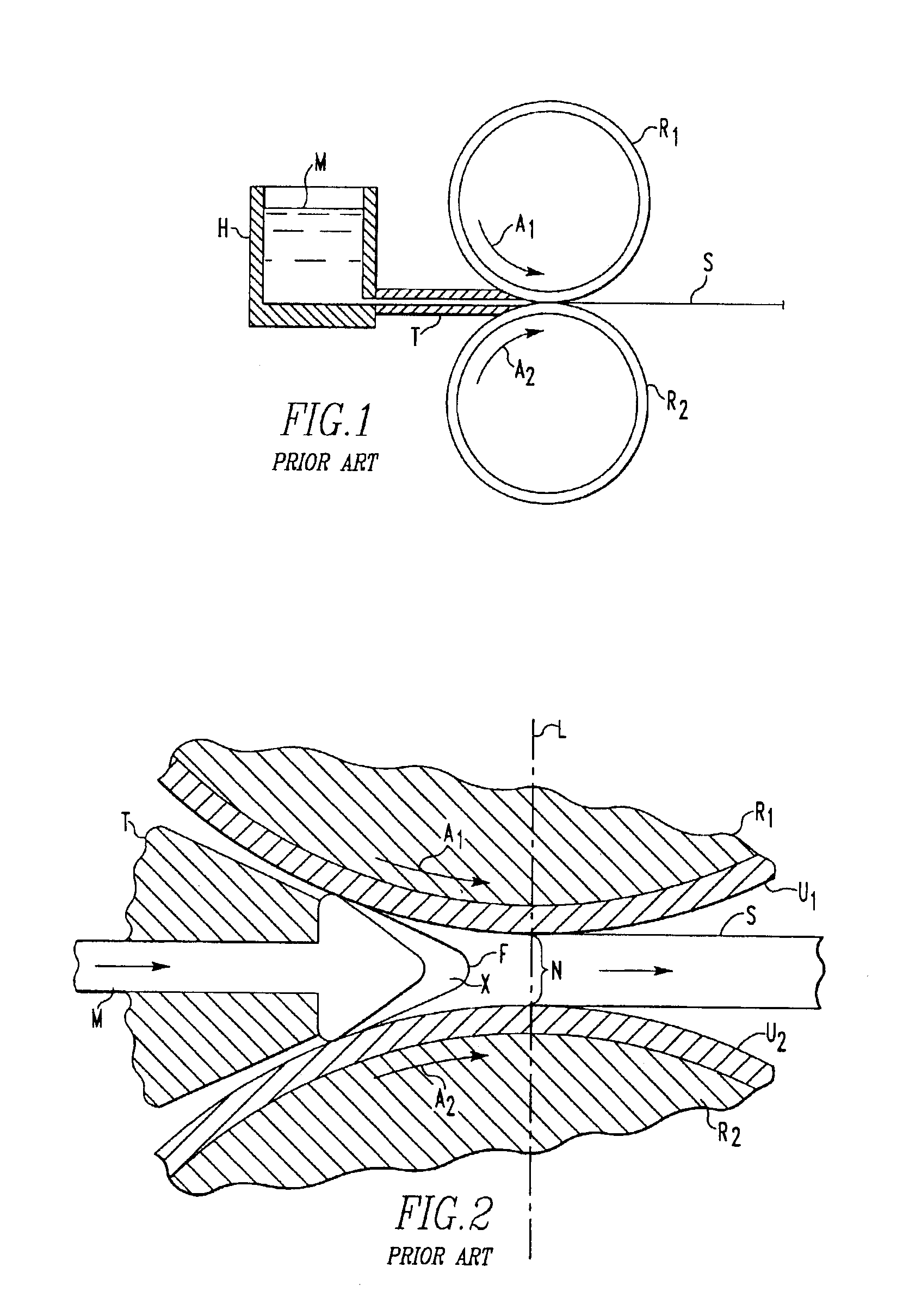
Attempts to increase the speed of roll casting typically fail due to centerline segregation.
Although it is generally accepted that reduced gauge sheet (e.g., less than about ¼ inch thick) potentially could be produced more quickly than higher gauge sheet in a roll caster, the ability to roll cast aluminum at rates significantly above about 70 lbs / hr / in has been elusive.
Extensive centerline segregation in the as-cast strip is a factor that restricts the speed of conventional roll casters.
Although some reduction in gauge is possible, operation at such high roll separating forces to ensure deformation of the strip at the nip N makes further reduction of the strip gauge very difficult.
Hence, the roll casting speed for aluminum alloys has been relatively low.
While this represents an advance in roll separating force reduction, these forces still pose significant process challenges.
Moreover, the productivity remains compromised and strip produced according to the '818 patent apparently exhibits some centerline segregation and grain elongation as shown in FIG. 3 thereof.
A major impediment to high-speed roll casting is the difficulty in achieving uniform heat transfer from the molten metal to the smooth surfaces U1 and U2, i.e., cooling of the molten metal.
At high rolling speeds, such non-uniformity in heat transfer becomes problematic.
For example, areas of the surfaces U1 and U2 with proper heat transfer will cool the molten metal M at the desired location upstream of the nip N whereas areas with insufficient heat transfer properties will allow a portion of the molten metal to advance beyond the desired location and create non-uniformity in the cast strip.
Although high speed casting of aluminum alloy strip is reported, a major drawback to this technique is that the delivery rate of the molten aluminum alloy must be carefully controlled to ensure uniformity in the cast strip.
In both cases, any variation in the gas pressure or delivery rate of the molten aluminum alloy results in non-uniformity in the cast strip.
The control parameters for this type of aluminum alloy roll casting are not practical on a commercial scale.
This may lead to distortion of the belts.
However, block casters require precise dimensional control to prevent gaps between the blocks which cause non-uniformity and defects in the cast strip.
The thickness of the strip can be limited by the heat capacity of the belts between which casting takes place.
However, problems associated with the belts used in conventional belt casting remain.
For any belt caster, conventional or heat sink type, contact of hot molten metal with the belts and the heat transfer from the solidifying metal to the belts creates instability in the belts.
Further, belts need to be changed at regular intervals which disrupts production.
Both processes require many material handling operations to move ingots and coils.
Such operations are labor intensive, consume energy and frequently result in product damage.
In addition, alloys other than aluminum such as magnesium alloys have not been continuously cast on a commercial scale.
Magnesium metal has a hexagonal crystal structure that severely restricts the amount of deformation that can be applied, particularly at low temperatures.
As a result, magnesium wrought products tend to be expensive.

Method used


Image

  • Casting of non-ferrous metals
  • Casting of non-ferrous metals
  • Casting of non-ferrous metals

Examples


examples

[0051]An aluminum alloy containing by wt. % 0.75 Si, 0.20 Fe, 0.80 Cu, 0.25 Mn and 2.0 Mg was cast according to the present invention and then hot and cold rolled in-line to 0.015 inch gauge. The resultant properties for two products are listed in Table 1. Example 1 shows properties obtained in the as-rolled condition after coil cooling. The combination of high strength and good formability (elongation) is notable. The combination of high yield strength and elongation achieved in Examples 1 and 2 has heretofore not been achieved in 5xxx series aluminum-magnesium alloys. By way of comparison, aluminum alloy 5182, at best, has a yield strength of 54 ksi and elongation of 7%. Example 2 shows properties obtained after the sheet was solution heat treated and aged at 275° F. in the laboratory. Good yield strength and superior bending properties were achieved.

[0052]

TABLE 1PropertyExample 1Example 2Yield strength (ksi)6043UTS (ksi)6555Elongation (%)1016Bend radius (r / t) 1.7 0.3*Ludering lin...


PUM

PropertyMeasurementUnit
Temperatureaaaaaaaaaa
Fractionaaaaaaaaaa
Linear densityaaaaaaaaaa

Abstract

A method of continuous casting non-ferrous alloys which includes delivering molten non-ferrous alloy to a casting apparatus. The casting apparatus rapidly cools at least a portion of the non-ferrous alloy at a rate of at least about 100° C. thereby solidifying an outer layer of the non-ferrous alloy surrounding an inner layer of a molten component and a solid component of dendrites. The dendrites are altered to yield cast product exhibiting good resistance to cracking.

Description

RELATED APPLICATIONS[0001]This application is a continuation-in-part of U.S. application Ser. No. 10 / 078,638 filed Feb. 19, 2002 now U.S. Pat. No. 6,672,368 entitled “Continuous Casting of Aluminum” which claims the benefit of U.S. Provisional Application Ser. No. 60 / 270,262 filed Feb. 20, 2001 entitled “Continuous Casting of Aluminum” and also claims the benefit of the following U.S. Provisional Applications: Ser. No. 60 / 405,333 filed Aug. 21, 2002 entitled “Magnesium Strip and Method of Continuous Casting Magnesium Base Alloys”, Ser. No. 60 / 405,359 filed Aug. 21, 2002 entitled “Titanium Strip and Method of Continuous Casting Titanium Base Alloys”, Ser. No. 60 / 406,453 filed Aug. 28, 2002 entitled “Casting of Non-Ferrous Metals”, Ser. No. 60 / 406,504 filed Aug. 28, 2002 entitled “Continuous Casting of Aluminum Strip for Making Automotive Sheet”, Ser. No. 60 / 406,505 filed Aug. 28, 2002 entitled “Continuous Casting of Aluminum Strip for Making Can Body Stock”, Ser. No. 60 / 406,506 filed...

Claims


Application Information

Patent Timeline
IPC IPC(8): B22F3/18B22D11/112B32B15/20B32B5/16C22F1/00B22D11/00B22D11/06
CPCB22D11/001B22D11/003B22D11/0605B22D11/0622Y10T428/12799Y10T428/12806Y10T428/12104Y10T428/12729Y10T428/12486
Inventor UNAL, ALI
Owner ARCONIC TECH LLC
Learn More