Voltage measurement device
a voltage measurement and voltage technology, applied in the direction of resistance/reactance/impedence, instruments, transportation and packaging, etc., can solve the problems of large current, large measurement device size and cost, and difficulty in accurately and quickly performing the switching operation of the condenser elements between charging and discharging, etc., to achieve excellent noise resistance capability, high speed, and high accuracy
- Summary
- Abstract
- Description
- Claims
- Application Information
AI Technical Summary
Benefits of technology
Problems solved by technology
Method used
Image

Examples
1st embodiment
1st Embodiment
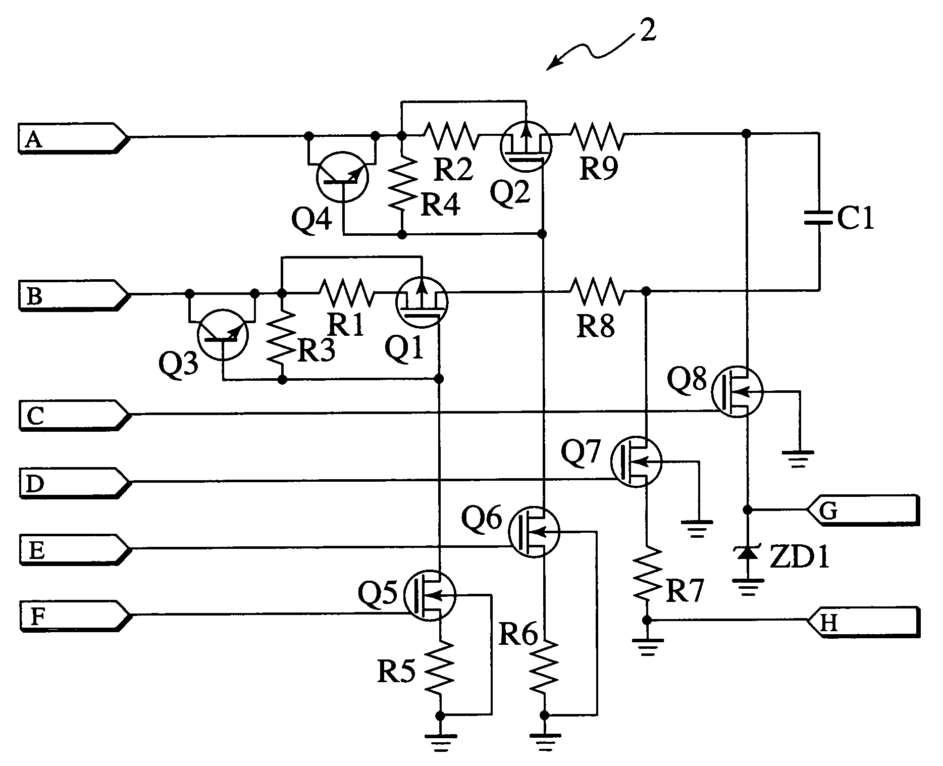
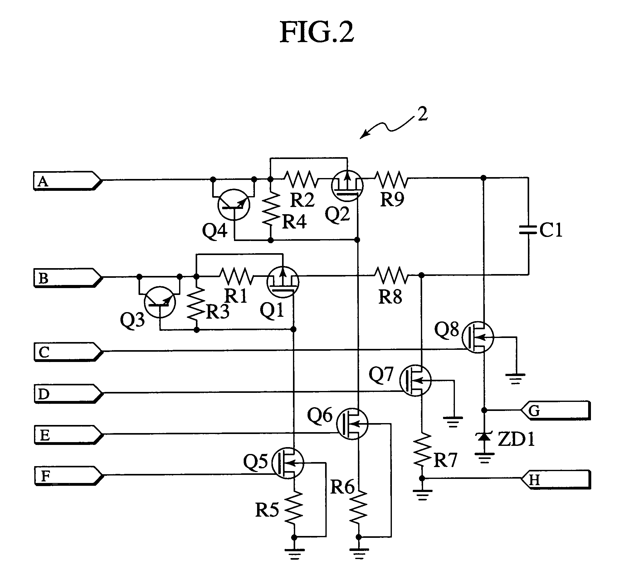
[0029]FIG. 2 is a circuit diagram showing a constitution of the voltage measurement circuit in the voltage measurement device of the first embodiment of the present invention. This voltage measurement circuit corresponds to each of the voltage measurement circuits 201˜20n shown in FIG. 1.
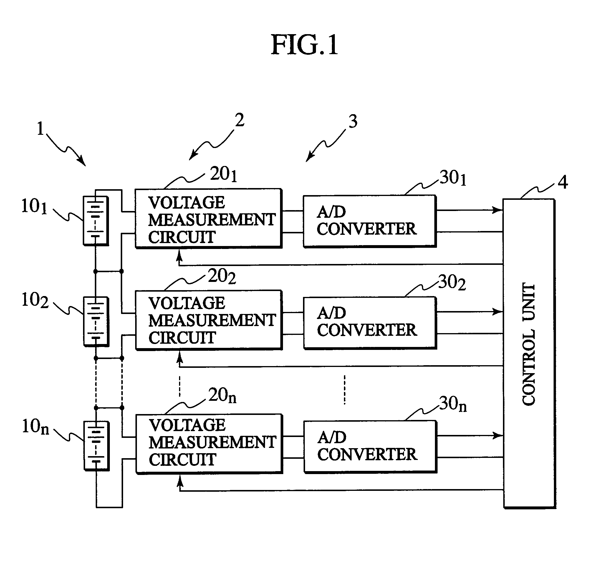
[0030]The voltage measurement circuit includes voltage input terminals A and B, control-signal input terminals C, D, E and F and voltage output terminals G and H. The voltage input terminal A is connected to one terminal (positive terminal) of a block of the plural blocks 101˜10n forming the battery 1, while the voltage input terminal B is connected to the other terminal (negative terminal) of the same block. The voltage output terminals G and H are connected to one A / D converter of the plural A / D converters 301˜30n. Further, the control-signal input terminals C, D, E and F are connected to the control unit 4.
[0031]This voltage measurement device includes a P-channel MOS field effect t...
2nd embodiment
2nd Embodiment
[0070]A voltage measurement device in accordance with the second embodiment of the present invention is provided to correct error voltage caused due to stray capacitances of switches etc. in view of speeding up a measurement cycle of the device.
[0071]FIG. 7 is a circuit diagram showing a constitution of a voltage measurement circuit in the voltage measurement device of the second embodiment. This voltage measurement circuit is provided by adding a control-signal input terminal I, a control-signal input terminal J, a voltage output terminal K and a dummy condenser C2 (corresponding to a second storage element of the invention) to the voltage measurement circuit of the first embodiment of FIG. 2 and further adding a high-voltage resistant Pch-MOSFET Q 9, a high-voltage resistant Nch-MOSFET Q 11 and a Nch-MOSFET Q 12 to the first group of switches, the third group of switches and the second group of switches, respectively. The dummy condenser C2 has one terminal connected...
3rd embodiment
3rd Embodiment
[0084]A voltage measurement device in accordance with the third embodiment of the present invention is provided to enable measurement of negative voltage.
[0085]FIG. 8 is a circuit diagram showing a constitution of a voltage measurement circuit in the voltage measurement device of the third embodiment. In this voltage measurement circuit, different from the voltage measurement circuit of the first embodiment of FIG. 2, the source of the Nch-MOSFET Q8 is connected to its back gate (substrate) and the voltage output terminal H is connected to ground through a zener diode ZD2. By use of the zener diode ZD2, it becomes possible to lift up potential of the voltage output terminal H, which will be used as reference potential in a subsequent stage, from ground potential by constant voltage with the use of a power source not shown. As a result, even if the potential difference between the voltage input terminals A and B both connected to the voltage source represents negative p...
PUM
| Property | Measurement | Unit |
|---|---|---|
| voltage | aaaaa | aaaaa |
| voltage | aaaaa | aaaaa |
| voltage measurement | aaaaa | aaaaa |
Abstract
Description
Claims
Application Information
 - R&D
- Intellectual Property
- Life Sciences
- Materials
- Tech Scout
- Unparalleled Data Quality
- Higher Quality Content
- 60% Fewer Hallucinations
Browse by: Latest US Patents, China's latest patents, Technical Efficacy Thesaurus, Application Domain, Technology Topic, Popular Technical Reports.
© 2025 PatSnap. All rights reserved.Legal|Privacy policy|Modern Slavery Act Transparency Statement|Sitemap|About US| Contact US: help@patsnap.com