Optical scanning apparatus

a scanning apparatus and optical technology, applied in the field of optical scanning apparatus, can solve the problems of expensive apparatus, poor beam performance, heavy beam, etc., and achieve the effect of not increasing the thickness of the deflector

Active Publication Date: 2006-10-24
KONICA MINOLTA INC
View PDF4 Cites 14 Cited by
  • Summary
  • Abstract
  • Description
  • Claims
  • Application Information

AI Technical Summary

Benefits of technology

[0020]Both in the optical scanning apparatus according to the first aspect of the present invention and in the optical scanning apparatus according to the second aspect of the present invention, it is preferred that the beams emitted from the respective light sources are incident to the deflector at a specified angle in a plane of sub-scanning. Thereby, it is possible to divide the beams into the upper optical system and the lower optical system without increasing the thickness of the deflector.

Problems solved by technology

Then, if the lenses are designed to correct the bows, other aberrations will become heavier, and the beam performance will be worse.
However, in the optical scanning apparatus according to this publication, lenses are exclusively used for each optical system, and therefore, the apparatus is costly.
Also, since beams are not incident to the deflector at an angle, the deflector must be made thick, which further increases the cost.

Method used


Image

  • Optical scanning apparatus
  • Optical scanning apparatus
  • Optical scanning apparatus

Examples


first and second embodiments

; See FIGS. 1–4

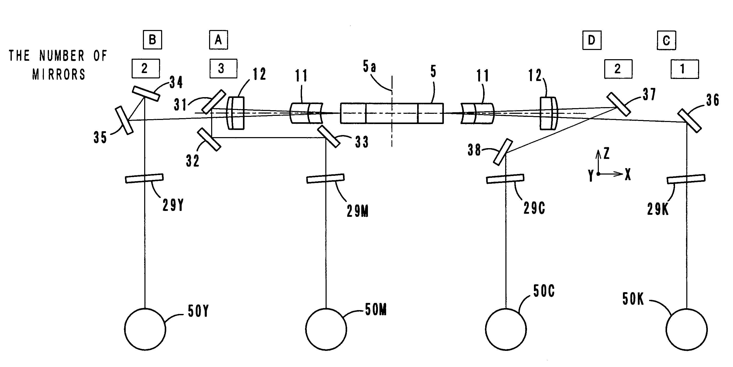
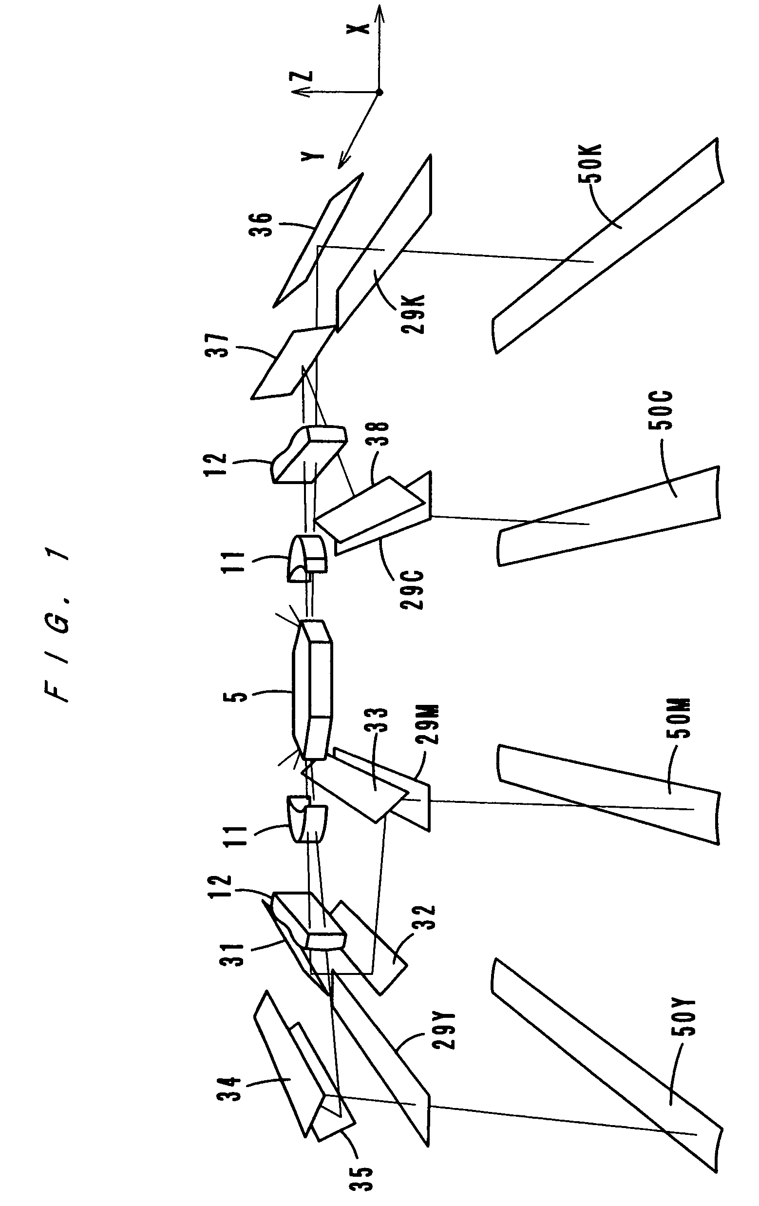
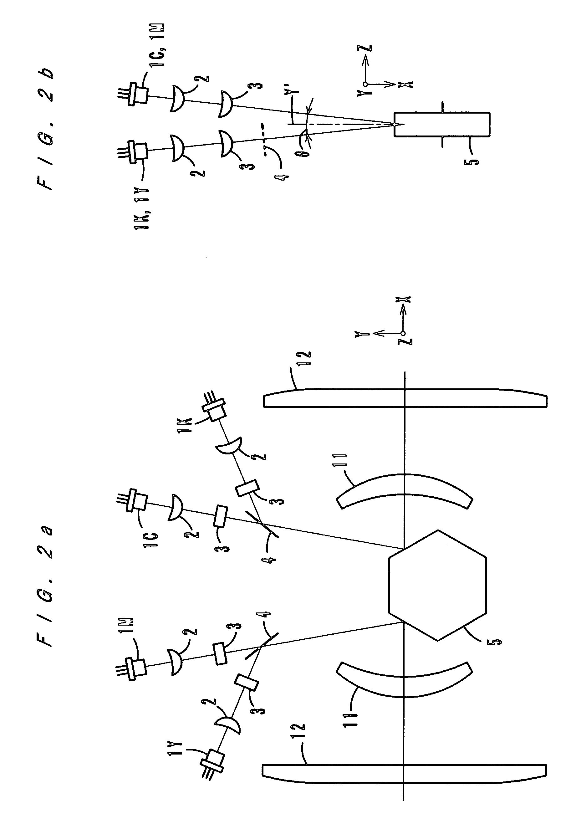
[0032]FIGS. 1–3 show an optical scanning apparatus according to a first embodiment of the present invention. FIG. 1 shows arrangement of elements three-dimensionally and conceptually, and FIG. 2 shows an optical path between a light source and a deflector. FIG. 3 is a sectional view in a sub-scanning direction. FIG. 4 is a sectional view taken in a sub-scanning direction of an optical scanning apparatus according to a second embodiment of the present invention.

first embodiment

[0033]The optical scanning apparatus is structured as an exposure scanning unit of an electrophotographic image forming apparatus of a tandem type, and as FIG. 3 shows, the optical scanning apparatus forms images for yellow, magenta, cyan and black respectively on four photosensitive drums 50 (50Y, 50M, 50C and 50K). The images (electrostatic latent images) formed on the photosensitive drums 50 are developed into toner images. Thereafter, the toner images are transferred onto an intermediate transfer belt and combined thereon with each other (first transfer). Then, the composite image is transferred onto a recording member (second transfer). This image forming process is well known, and a description thereof is omitted.

[0034]As FIGS. 2a and 2b show, the optical scanning apparatus has four light source units, each of which comprises a laser diode 1, a collimator lens 2 and a cylindrical lens 3, arranged respectively in the right upper side, in the right lower side, in the left upper...

second embodiment

[0041] regarding the number of diverting mirrors 41 through 46, as FIG. 4 shows, the number A of mirrors located in the upper optical path at one side (in the optical path for yellow) is one, and the number B of mirrors located in the lower optical path at the same side (in the optical path for magenta) is two. The number C of mirrors located in the upper optical path at the other side (in the optical path for black) is one, and the number D of mirrors located in the upper optical path at the same side (in the optical path for cyan) is two.

[0042]Thus, in the left side of the polygon mirror 5, the number A of diverting mirrors located in the upper optical path and the number B of diverting mirrors located in the lower optical path are one and two respectively, that is, an odd number and an even number. In the right side of the polygon mirror 5, the number C of diverting mirrors located in the upper optical path and the number D of diverting mirrors located in the lower optical path a...


PUM


Abstract

An optical scanning apparatus comprising a plurality of light sources, a polygon mirror for deflecting beams emitted from the light sources in a main scanning direction, lenses for imaging the deflected beams on receiving surfaces and diverting mirrors for directing the beams which passed through the lenses to the receiving surfaces. In one side of the polygon mirror, three diverting mirrors are provided in an upper optical path, and two diverting mirrors are provided in a lower optical path. In the other side of the polygon mirror, one diverting mirror is provided in a lower optical path, and two diverting mirrors are provided in an upper optical path. Thereby, bows on the receiving surfaces have the same curving direction, and color displacement can be inhibited.

Description

[0001]This application is based on Japanese application No. 2005-148192 filed on May 20, 2005 and Japanese application No. 2005-148195 filed on May 20, 2005, the contents of which are incorporated by reference.BACKGROUND OF THE INVENTION[0002]1. Field of the Invention[0003]The present invention relates to an optical scanning apparatus, and more particularly to an optical scanning apparatus for scanning a plurality of beams modulated in accordance with image data on receiving surfaces by use of a single deflector.[0004]2. Description of Related Art[0005]In recent years, in the field of image forming apparatuses, such as full-color copying machines, printers, etc., a tandem type is general. In the tandem type, four photosensitive members respectively for Y (yellow), M (magenta), C (cyan) and K (black) are arranged in parallel, and images in the respective colors formed on the photosensitive members are transferred onto an intermediate transfer belt so that the color images can be comb...

Claims


Application Information

Patent Timeline
Patent Type & Authority Patents(United States)
IPC IPC(8): G02B26/08
CPCG02B26/123G02B26/125
Inventor KINOSHITA, HIROKIOOKI, MAKOTOSUGIMARU, YOSHIKI
Owner KONICA MINOLTA INC
Why Eureka
Try Eureka