Method and apparatus for network analysis, such as analyzing and correlating identifiers of frame relay circuits in a network

Inactive Publication Date: 2006-10-24
MICROSOFT TECH LICENSING LLC
View PDF21 Cites 9 Cited by
  • Summary
  • Abstract
  • Description
  • Claims
  • Application Information

AI Technical Summary

Benefits of technology

[0009]The present invention solves the above problems of how to determine matching DLCIs of frame relay circuits. More specifically, the present invention allows a user to analyze a telecommunications network having virtual private network segments, such as frame relay circuits, where standard network analysis tools fail to identify such segments. Standard network discovery tools identify segments such as frame relay circuits, but provide no information about which circuits are connected to each other. The present invention comprises a facility that can gather statistical data with respect to frame relay circuits. Based on such statistical data, the facility can match end points of the circuits with corresponding starting points. Thus, a network designer or manager can use standard and less expensive hardware in networks employing frame relay circuits, and other virtual private network segments, by employing the facility of the present invention to fully document and verify the overall configuration of the network environment, without prior knowledge of the network's makeup.
[0011]More specifically, the facility of the present invention can employ several inverse pairs of statistics to create statistical fingerprints for each DLCI. The inverse pairs of statistics can reduce the possibility of random matches between unmatched DLCIs. Typically, the core statistics at one end of a DLCI will match the inverse core statistics at the other end of the circuit indicating a match. For example, one DLCI can report 2.43 megabytes transmitted while another DLCI can report the same or similar number of bytes received during the polling interval. Similarly, the same DLCI can reports three send errors, while the other DLCI can report three receive errors. The facility of the present invention can initially assume that the number of bytes sent down one end of the frame relay circuit (associated with one DLCI) will usually closely match the number of bytes coming out or received at the other end (associated with another DLCI), taking into account data loss through the public switch telephone network. Likewise, the facility of the present invention can assume the number of errors received at one end of the DLCI will match the number of send errors at the other DLCI.
[0013]The facility can also perform at least one verification step. The facility of the present invention can poll the suspected DLCI pair in sequence to (or adjacent in time) to obtain data from appropriate counters as contemporaneously as possible. By obtaining data from appropriate counters as contemporaneously as possible, the facility can help eliminate statistical skew that can occur between respective pairs of DLCIs. For example, to obtain a first match between a pair of DLCIs, facility of the present invention can employ a first polling period of a first duration. In the verification step, the facility of the present invention can employ a second polling period of second duration which is substantially shorter than the first polling period of the first duration. In this way, a skew time interval comprising the time period between the polling of DLCIs of a DLCI pair can be reduced to as close to zero as possible.

Problems solved by technology

Standard network discovery tools identify segments such as frame relay circuits, but provide no information about which circuits are connected to each other.

Method used


Image

  • Method and apparatus for network analysis, such as analyzing and correlating identifiers of frame relay circuits in a network
  • Method and apparatus for network analysis, such as analyzing and correlating identifiers of frame relay circuits in a network
  • Method and apparatus for network analysis, such as analyzing and correlating identifiers of frame relay circuits in a network

Examples


Embodiment Construction

[0018]A network analysis facility, and in particular, an apparatus and related method for analyzing telecommunications networks having virtual private network segments, is described in detail herein. In the following description, numerous specific details are provided, such as specific network data, steps, etc., to provide a thorough understanding of embodiments of the invention. One skill in the relevant art, however, will recognize that the invention can be practiced without one or more of these specific details, or with data, steps, etc. In other instances, well-known structures or operations are not shown, or not described in detail, to avoid obscuring aspects of the invention.

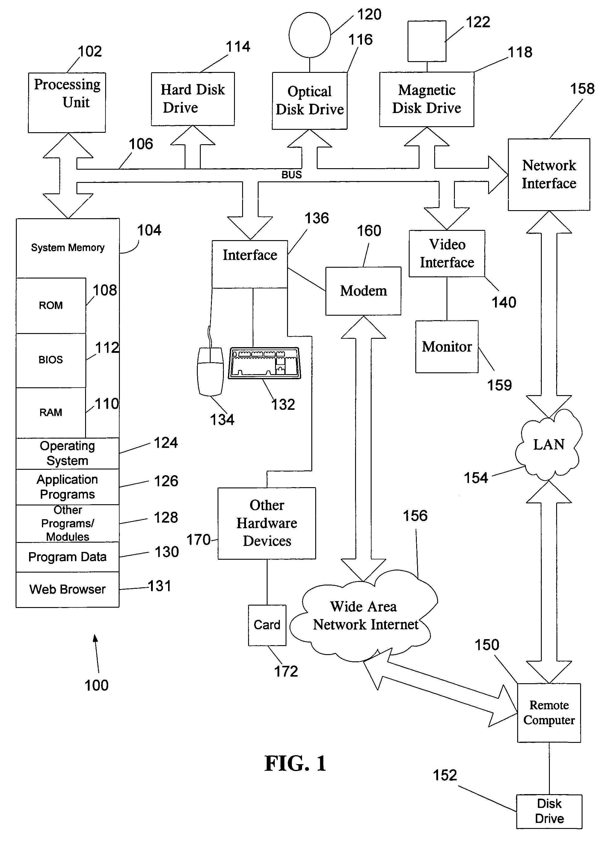
[0019]FIG. 1 and the following discussion provide a brief, general description of a suitable computing environment in which the invention can be implemented. Although not required, embodiments of the invention will be described in the general context of computer-executable instructions, such as program mod...


PUM


Abstract

A system, method or facility allow a user to analyze a telecommunications network having virtual private network segments, such as frame relay circuits, where standard network analysis tools fail to identify such circuits. The facility receives identifiers or addresses for such circuits and gathers statistical data with respect thereto. Based on such statistical data, the facility matches end points of the circuits with corresponding starting points. Thus, a network designer or manager may use standard and less expensive hardware in networks employing frame relay circuits, and other virtual private network segments, by employing the facility to fully document and verify the overall configuration of the network environment, without prior knowledge of the network's makeup.

Description

CROSS REFERENCE TO RELATED APPLICATION[0001]This application claims benefit of priority to U.S. Provisional Application No. 60 / 181,954, entitled, “METHOD AND APPARATUS FOR NETWORK ANALYSIS, SUCH AS ANALYZING AND CORRELATING IDENTIFIERS OF FRAME RELAY CIRCUITS IN A NETWORK,” filed Feb. 11, 2000.TECHNICAL FIELD[0002]The invention relates generally to analyzing networks. More specifically, the invention relates to the mapping of frame relay circuits in computer networks.BACKGROUND OF THE INVENTION[0003]Network managers and other technology specialists must often manage complex networks. These networks include numerous components such as switches, routers, gateways and terminating equipment such as work stations, personal computers (PCs), servers, and the like.[0004]Some computer software systems exist to analyze and diagram elements of a network. Examples of such systems are Visio Enterprise™ by Visio Corporation and OpenView™ by Hewlett-Packard Corporation. These systems analyze a net...

Claims


Application Information

Patent Timeline
IPC IPC(8): H04L12/28G01R31/08G06F11/00G08C15/00H04J1/16
CPCH04L12/24H04L41/00H04L41/0213H04L41/0233H04L41/06H04L41/0866H04L41/142
Inventor ERWIN, JEFF B.
Owner MICROSOFT TECH LICENSING LLC
Why Eureka
Try Eureka