
Method and apparatus for generating an aerosol

Inactive Publication Date: 2006-10-31
PHILIP MORRIS USA INC
View PDF211 Cites 88 Cited by
  • Summary
  • Abstract
  • Description
  • Claims
  • Application Information

AI Technical Summary

Benefits of technology

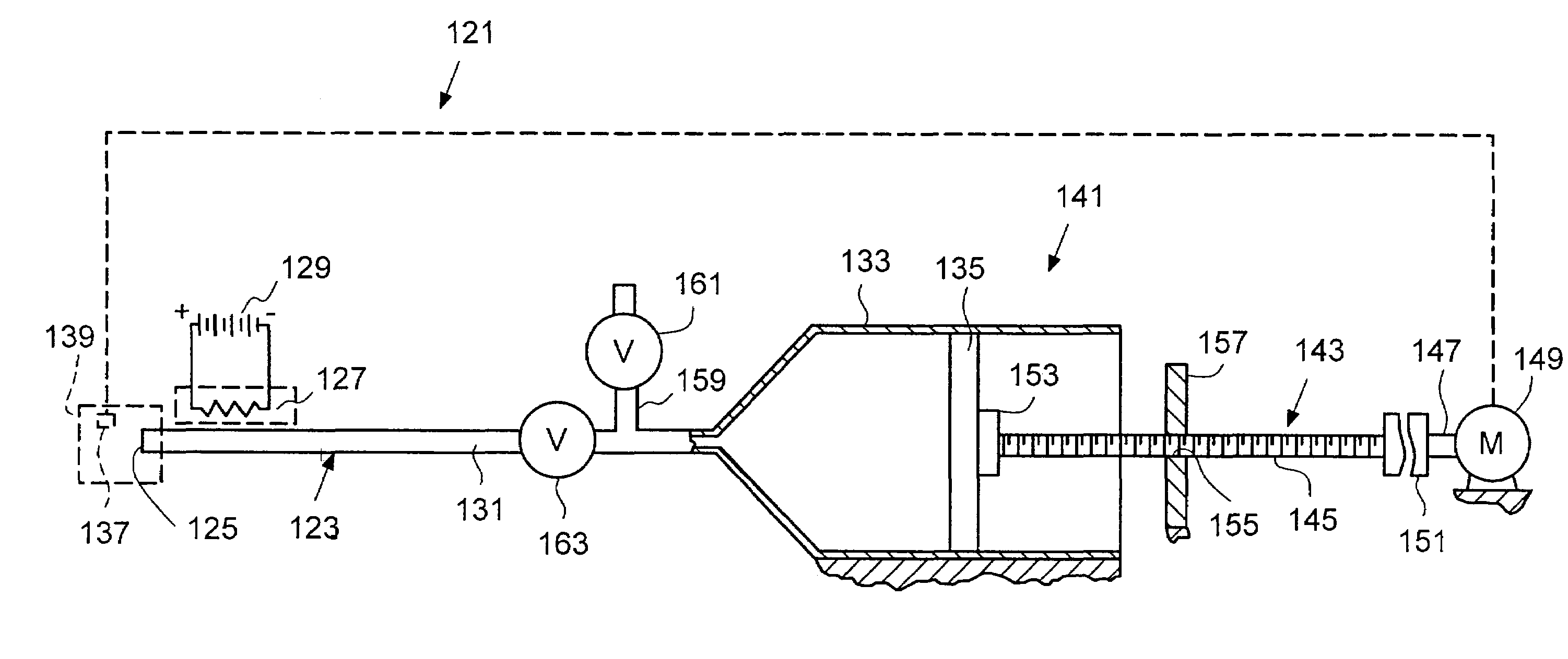
[0014]In accordance with another embodiment of the present invention, a spacer chamber can be added at the open end of the flow passage. Such a spacer chamber facilitates the enlargement of the mass median aerosol diameter of the aerosol particles generated.

Problems solved by technology

Both of these methods of generating an aerosol for the delivery of medicaments suffer from problems.
The aerosols produced by these techniques contain substantial quantities of particles or droplets which are too large to be inhaled.
Further, it is difficult to synchronize the inhalation of the medicament with the pumping of the aerosol device or the release of the powder.
Persons who have difficulty in generating a sufficient flow of air through the device to properly inhale the medicaments, such as asthma or emphysema sufferers, have particular difficulty in using these devices.
However, it is again difficult to properly synchronize the inhalation of the medicament with depression of the actuator.
Further, large quantities of medicament or other materials are not suitably delivered by this method.
Most known aerosol generators also are unable to generate aerosols having an average mass median aerosol diameter (MMAD) less than 2 to 4 microns, and are incapable of delivering high flow rates, such as above 1 milligram per second, with particles in the range of 0.2 to 2.0 microns.
Further, what is inhaled may not penetrate the lungs deeply enough.
Thus, loss of medicament occurs within spacer chambers and is a drawback to effective spacer chamber use.
However, like other aerosol generators, some material can be lost during aerosol generation to the CAG device itself.
Further, if used to deliver medicament to the lungs of a patient, some aerosolized medicament can be lost to the throat and mouth of the patient.
Because the CAG produces very fine particles, the particles may potentially be exhaled before settling fully into the patient's lungs, diminishing the amount of medicament delivered to the patient.

Method used


Image

  • Method and apparatus for generating an aerosol
  • Method and apparatus for generating an aerosol
  • Method and apparatus for generating an aerosol

Examples


examples

[0088]The Examples were conducted with the apparatus and in the methods described below unless otherwise indicated.

[0089]For purposes of performing experiments in connection with the aerosol generator described herein, a laboratory unit was designed which contained the basic elements of the generator, but which was modular in construction so that the various components could be exchanged after running. During most of the runs it was possible to measure the surface temperature of the heater and the power applied. Mass median aerosol diameter was obtained using a cascade impactor in accordance with the methods specified in the “Recommendations of the USP Advisory Panel on Aerosols on the General Chapters on Aerosols (601) and Uniformity of Dosage Units (905),”Pharmacopeial Forum. Vol. 20, No. 3, pp. 7477 et. seq. (May–June 1994), and aerosol mass was measured gravimetrically or chemically by HPLC as collected from the impactor.

[0090]In the Examples that follow, the aerosol generator i...


PUM

PropertyMeasurementUnit
Fractionaaaaaaaaaa
Pressureaaaaaaaaaa
Diameteraaaaaaaaaa

Abstract

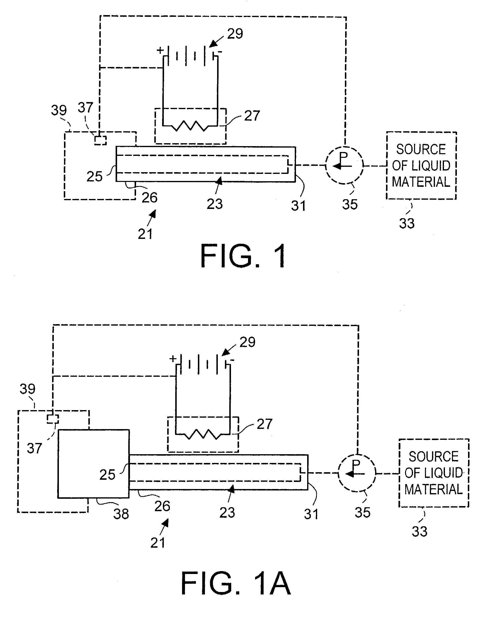
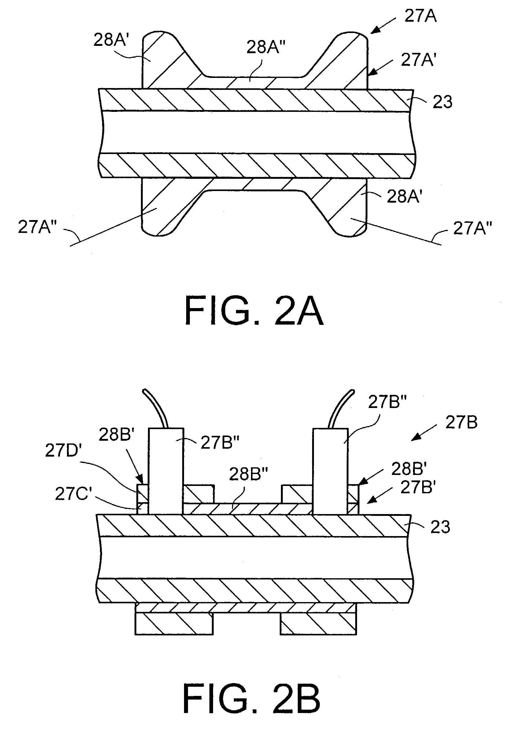
An aerosol is formed by supplying a material in liquid form to a flow passage and heating the flow passage such that the material volatizes and expands out of an open end of the flow passage. The volatized material combines with ambient air such that volatized material condenses to form the aerosol. An apparatus and method for generating such an aerosol are disclosed wherein the apparatus may include an electrically conductive sleeve at an open end of the flow passage, an electrically conductive flow passage and / or a spacer chamber. The volatilized material may contain a volatilized solute and vehicle such that the resulting aerosol particle sizes of the solute and the vehicle are either different or the same.

Description

[0001]This application is a continuation of application Ser. No. 09 / 560,510, filed on Apr. 27, 2000 now abandoned.[0002]The present invention relates generally to an apparatus and method for generating aerosols without compressed gas propellants.BACKGROUND OF THE INVENTION[0003]Aerosols are useful in a wide variety of applications. For example, it is often desirable to treat respiratory ailments with, or deliver medicaments by means of, aerosol sprays of finely divided particles of liquid and / or solid, such as powders, liquid medicaments, and the like, which are inhaled into a patient's lungs. Aerosols are also used for such purposes as providing desired scents to rooms, applying scents to the skin, and delivering paint and lubricant, for example.[0004]Various techniques are known for generating aerosols, particularly in the field of medicine. For example, U.S. Pat. Nos. 4,811,731 and 4,627,432 both disclose devices for administrating medicaments to patients in which a capsule is pi...

Claims


Application Information

Patent Timeline
IPC IPC(8): A61M15/00B67D5/62H05B3/00A61K9/72A61K31/573A61K47/10A61M11/00A61M11/04A61M16/00A61M16/10B67D7/80
CPCA61M11/041A61M11/042A61M16/109A61M11/007A61M2016/0024A61M2205/8206
Inventor BYRON, PETER R.HINDLE, MICHAEL
Owner PHILIP MORRIS USA INC
Learn More