Connecting structure and its connecting method, and rotating machinery and alternating current

a technology of connecting structure and connecting method, which is applied in the direction of windings, assembly for rectification, manufacturing tools, etc., can solve the problems of reducing the reliability of connecting strength, mechanical strength is reduced, and the cross-section of electric cables is reduced. , to achieve the effect of preventing local heat generation

Inactive Publication Date: 2006-10-31
HITACHI ASTEMO LTD
View PDF25 Cites 6 Cited by
  • Summary
  • Abstract
  • Description
  • Claims
  • Application Information

AI Technical Summary

Benefits of technology

[0011]It is a further object of the present invention that during the application of the current comes through the electrically conducted member, the local heating of the connecting terminal is prevented so that the whole connecting terminal is heated uniformly.
[0020]By means of the connecting structure and the connecting method of the present invention, it will be appreciated that the electrically conductive member and the connecting terminal can be downsized, and further that the connecting quality can be stabilized.

Problems solved by technology

In the connecting method in which the coating is mechanically removed, however, it is difficult to remove the coating completely and constantly and the electric cable having the insulated coating may be damaged, which leads to the reduction in the cross-section of the electric cable and hence the reduction in the reliability for connecting strength.
The chemical connecting method gives a great effect to safety and environmental issues, and the solder-based connecting method has such a problem that the mechanical strength is reduced in a high temperature, both of which leads to reduction in the reliability.
In addition, in such a connecting method as the coating is not removed and the connecting support member is not used, only the electric cable and the electrically conductive member contact mechanically to each other but the metallic contact is not established.
Though the electrical connectivity is guaranteed by caulking the electrically conductive member, there found such a problem in the electrical characteristic and the strength reliability because the caulking strength is reduced due to vibration or heat cycle.
However, as what is inserted in the terminal formed in U-shape or in a round form is the electric cable having the insulated coating, the applied electric current is concentrated at the bending or curvature part and thus there is such a problem that this part is overheated, melt down or buckled.

Method used


Image

  • Connecting structure and its connecting method, and rotating machinery and alternating current
  • Connecting structure and its connecting method, and rotating machinery and alternating current
  • Connecting structure and its connecting method, and rotating machinery and alternating current

Examples


embodiment 1

(Embodiment 1)

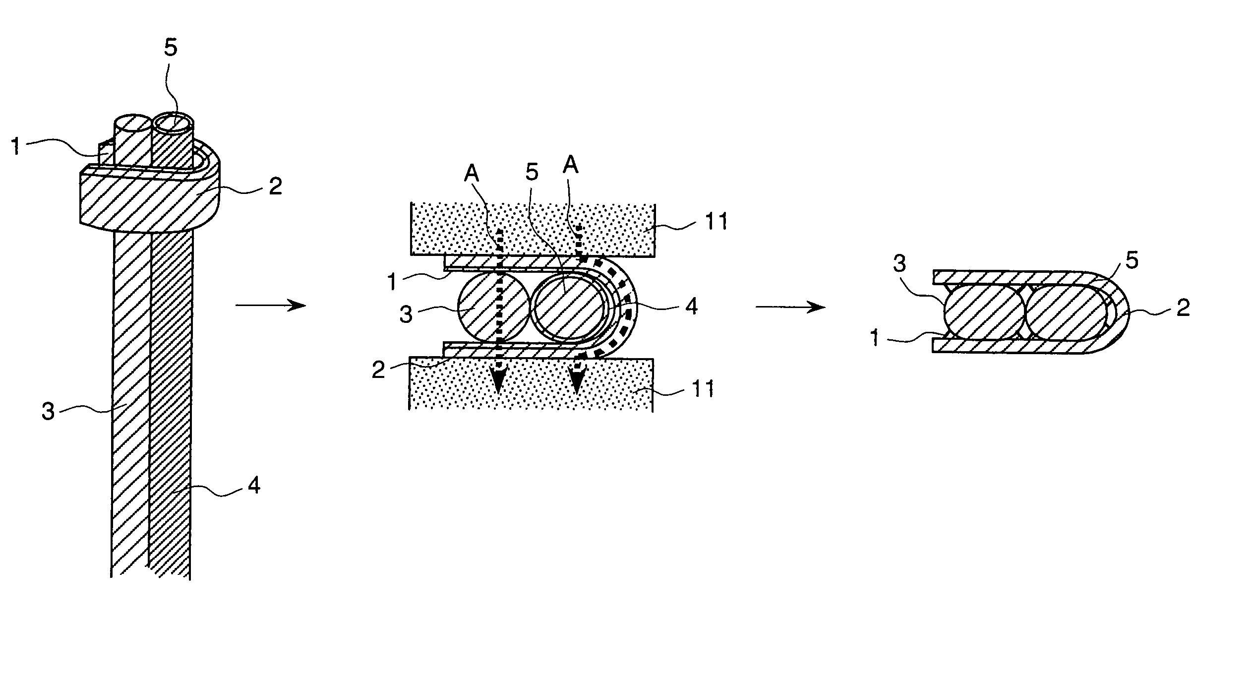
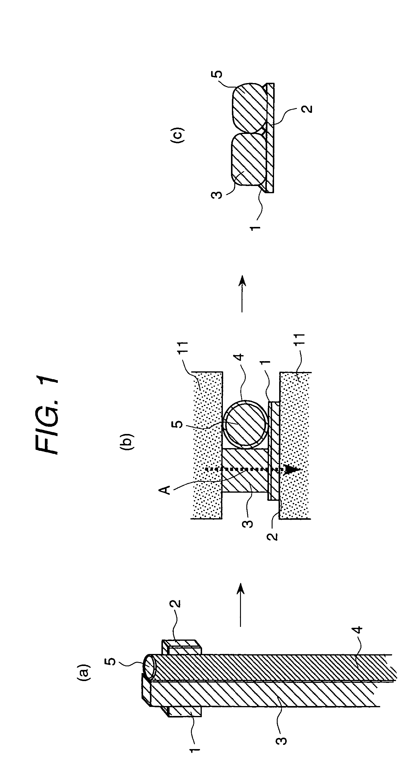
[0045]In this embodiment, as shown in FIG. 1(a), the electric cable 5 having the insulated coating and the electrically conductive member 3 are arranged on the connecting terminal 2 on which the junction support member 1 is installed in advance. Next, as shown in FIG. 1(b), the electrode 11 for the resistance welding applies the press. At this point, the electric cable 5 having the insulated coating, the electrically conductive member 3 and the connecting terminal 2 are pressed so as to contact to the electrode 11. After that, applying the electric current to the electrode 11, the electric current A flows through the electrically conductive member 3, and then the electrode 11, the electrically conductive member 3 and the junction support member 1 generates heat. Owing to this heat generation, the insulated coating 4 gets soften, and is removed by the applied pressure of the electrode 11, and then the electric cable 5 having the insulated coating and the electrically co...

embodiment 2

(Embodiment 2)

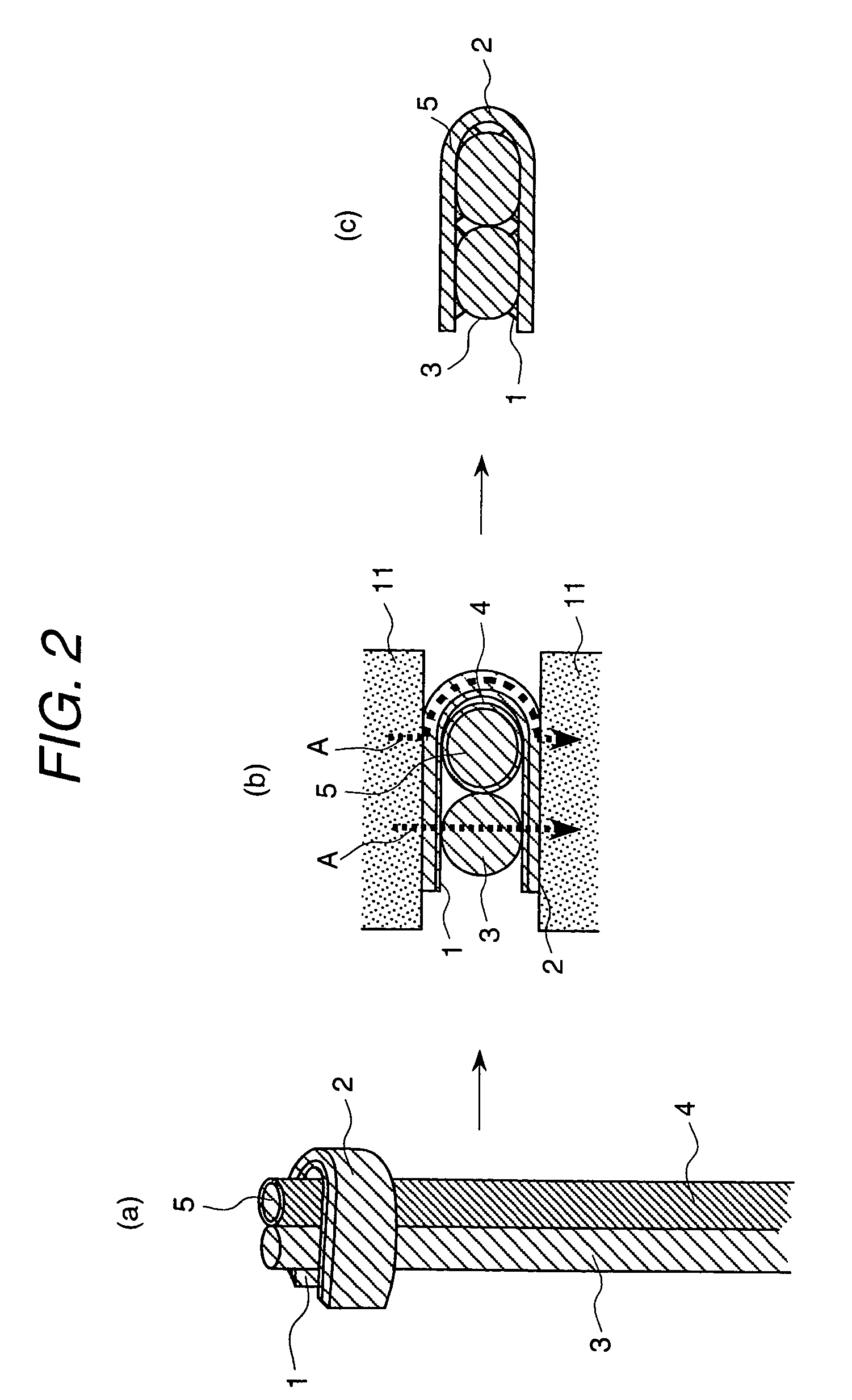
[0047]In this embodiment, as shown in FIG. 2(a), the electric cable 5 having the insulated coating and the electrically conductive member 3 are inserted in parallel into the connecting terminal 2 having the junction support member 1 in advance in its U-shaped inside surface.

[0048]In this process, it is preferable that the electrically conductive member 3 is arranged at the open port side of the connecting terminal 2. Next, as shown in FIG. 2(b), the electrode 11 for the resistance welding presses the electric cable 5 having the insulated coating and the electrically conductive member 3 so as to contact individually to the opposed surface of the connecting terminal 2 formed in U-shape. After that, applying the electric current to the electrode 11, the electric current A flows through the bending part of the connecting terminal 2 formed in U-shape and the electrically conductive member 3. As this electric current flows separately in two parts, the electric current is not...

embodiment 3

(Embodiment 3)

[0050]In this embodiment, the electrically conductive member 3 is shaped in a round form as shown in FIG. 3, the connecting terminal 2 is shaped in an arched form as shown in FIG. 4, and the connecting terminal 2 is shaped in an rectangular open channel formed as shown in FIG. 5. This embodiment can establish the same junction state as the method shown in the embodiment 1, and provides the same effect.


PUM

PropertyMeasurementUnit
weight fractionaaaaaaaaaa

Abstract

A connecting structure in which the electric cable having an insulated coating and the electrically conductive member with non-insulated coating are connected through a connecting terminal having a junction support member by applying an electric current, heating and applying a pressure; and the electric cables having an insulated coating and are connected mutually to one another through a connecting terminal having an electrically conductive member with non-insulated coating and a junction support member by applying an electric current, heating and applying a pressure, and a connecting method in which those connections are established by applying an electric current, applying a heat and applying a pressure, and a rotating electric machinery having that connecting structure and an alternating current generator using this machinery.

Description

[0001]This application is a continuation of application Ser. No. 10 / 247,762, filed Sep. 20, 2002 now abandoned.BACKGROUND OF THE INVENTION[0002]The present invention relates to a new connecting structure and its connection method, and to a rotating electrical machinery having the above connecting structure and an alternating current generator using this rotating electrical machinery.[0003]Conventionally, the connecting method for the cable having an insulated coating for the electrical machinery includes the insulated coating of the electric cable having the insulated coating is removed by a mechanical or chemical method, and the electric cable with its metallic surface being exposed is made wound around the electrically conductive member.[0004]As for the connecting method for connecting directly the electric cable to the electrically conductive member without removing the insulated coating of the electric cable having the insulated coating, using a U-shaped electrically conductive ...

Claims


Application Information

Patent Timeline
Patent Type & Authority Patents(United States)
IPC IPC(8): H01R4/02H01R39/32H01R39/00H01R43/02H02K3/04H02K3/50H02K3/52H02K5/22H02K11/04
CPCH01R43/0228H02K3/528H02K11/046H01R39/32H02K3/50H02K5/225H02K11/05
Inventor ONOSE, SHINTERAKADO, KATSUYOSHIISHIKAWA, FUMINORIKASE, MASAMICHIOKAMURA, MASAKI
Owner HITACHI ASTEMO LTD
Why Eureka
Try Eureka