Apparatus for generating a plurality of beamlets

a technology of charged particle and apparatus, which is applied in the field of apparatus for generating a plurality of charged particle beamlets, can solve the problems of affecting the performance of the system, the angle of the charge particle beamlet change is not exactly defined,

Active Publication Date: 2006-10-31
ASML NETHERLANDS BV
View PDF9 Cites 287 Cited by
  • Summary
  • Abstract
  • Description
  • Claims
  • Application Information

AI Technical Summary

Benefits of technology

[0060]FIGS. 10A, 10B show t...

Problems solved by technology

However, the change of angle of a charged particle beamlet is not exactly defined due to so-...

Method used


Image

  • Apparatus for generating a plurality of beamlets
  • Apparatus for generating a plurality of beamlets
  • Apparatus for generating a plurality of beamlets

Examples


Embodiment Construction

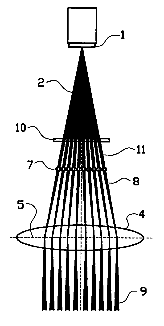
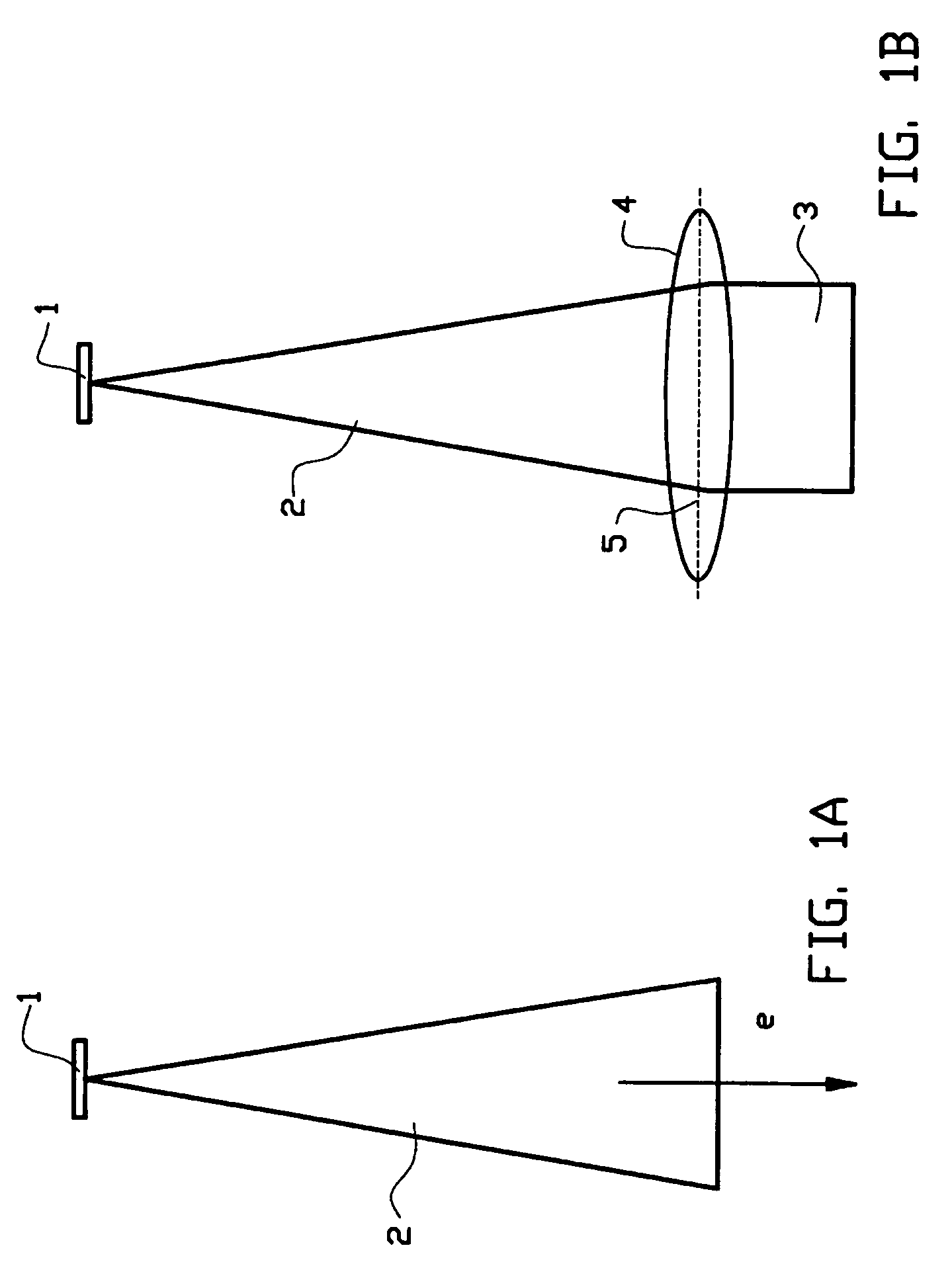
[0061]FIG. 1A shows an arbitrary source 1 that emits a diverging charged particle beam 2. In a variety of systems not a diverging beam 2, but a collimated beam 3, i.e. a beam, which is substantially parallel, is desired. Therefore a collimator lens 4 as shown (schematically) in FIG. 1B or collimation assembly is positioned in the beam trajectory to collimate the diverging charged particle beam 2. The collimation takes place in the collimation plane or principal plane 5 of the collimator 4, denoted in FIG. 1B by the dotted line. After collimation the (almost) parallel charged particle beam can be split in a plurality of beamlets, which are subsequently focused on a target for pattern exposure, inspection, observation or other purposes.

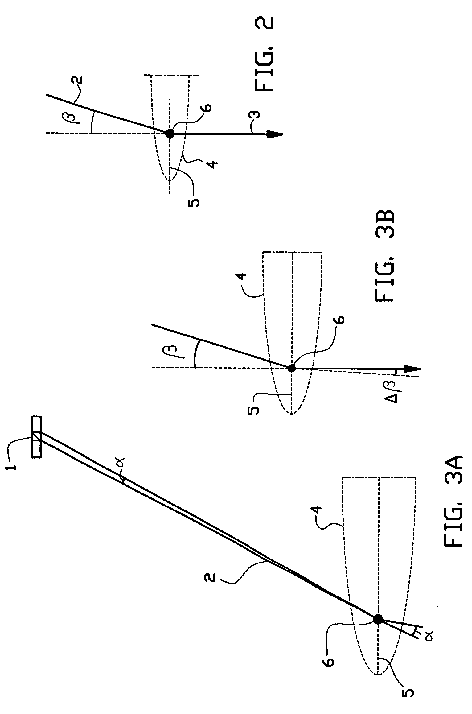
[0062]In the collimation plane or principal plane 5, an incoming charged particle beam is refracted to create a collimated beam. FIG. 2 shows the trajectory of a small portion of the diverging charged particle beam 2, which is refracted in the collimato...


PUM


Abstract

The invention relates to an apparatus for generating a plurality of charged particle beamlets, comprising a charged particle source for generating a diverging charged particle beam, a converging means for refracting said diverging charged particle beam and a lens array comprising a plurality of lenses, wherein said lens array is located between said charged particle source and said converging means.
In this way, it is possible to reduce aberrations of the converging means.

Description

[0001]This application claims the benefit of U.S. Provisional Application No. 60 / 453,745, filed Mar. 10, 2003.BACKGROUND[0002]The present invention relates to an apparatus for generating a plurality of charged particle beamlets. Charged particle beams are used in a variety of systems, like lithography and microscopy systems. Some of these systems use a single source generating one beam which is subsequently split into a plurality of beamlets. The charged particle source used in these systems emits a charged particle beam with a defined opening angle, i.e. a diverging beam. The diverging beam often needs to be collimated, i.e. transformed into a parallel beam. In most applications a lens or lens assembly is used to refract the diverging beam emitted.[0003]However, the change of angle of a charged particle beamlet is not exactly defined due to so-called chromatic aberrations. As a result the spot size of the beamlets on the target to be exposed or imaged also increases.[0004]In GB2340...

Claims


Application Information

Patent Timeline
IPC IPC(8): H01J37/04G09GH01J3/02H01J3/07H01J3/14H01J3/26H01J37/063H01J37/317
CPCB82Y10/00B82Y40/00H01J3/07H01J37/063H01J37/12H01J37/153H01J37/3174H01J37/3177H01J2237/1205H01J2237/151H01J2237/1536H01J2237/26H01J2237/31774H01J37/317
Inventor KRUIT, PIETER
Owner ASML NETHERLANDS BV
Why Eureka
Try Eureka