Apparatus for controlled movement of an element
- Summary
- Abstract
- Description
- Claims
- Application Information
AI Technical Summary
Benefits of technology
Problems solved by technology
Method used
Image

Examples
Embodiment Construction
[0053]It should be stated at the outset that the invention is susceptible of many embodiments and is applicable to other and various uses where dynamic control of the directional orientation from a reference point, of a very small platform or device is needed, particularly with little or no power required to hold a desired position once acquired. What follows is merely a description of a preferred embodiment, and should not be construed as limiting of the scope of the invention.
Ball and Socket
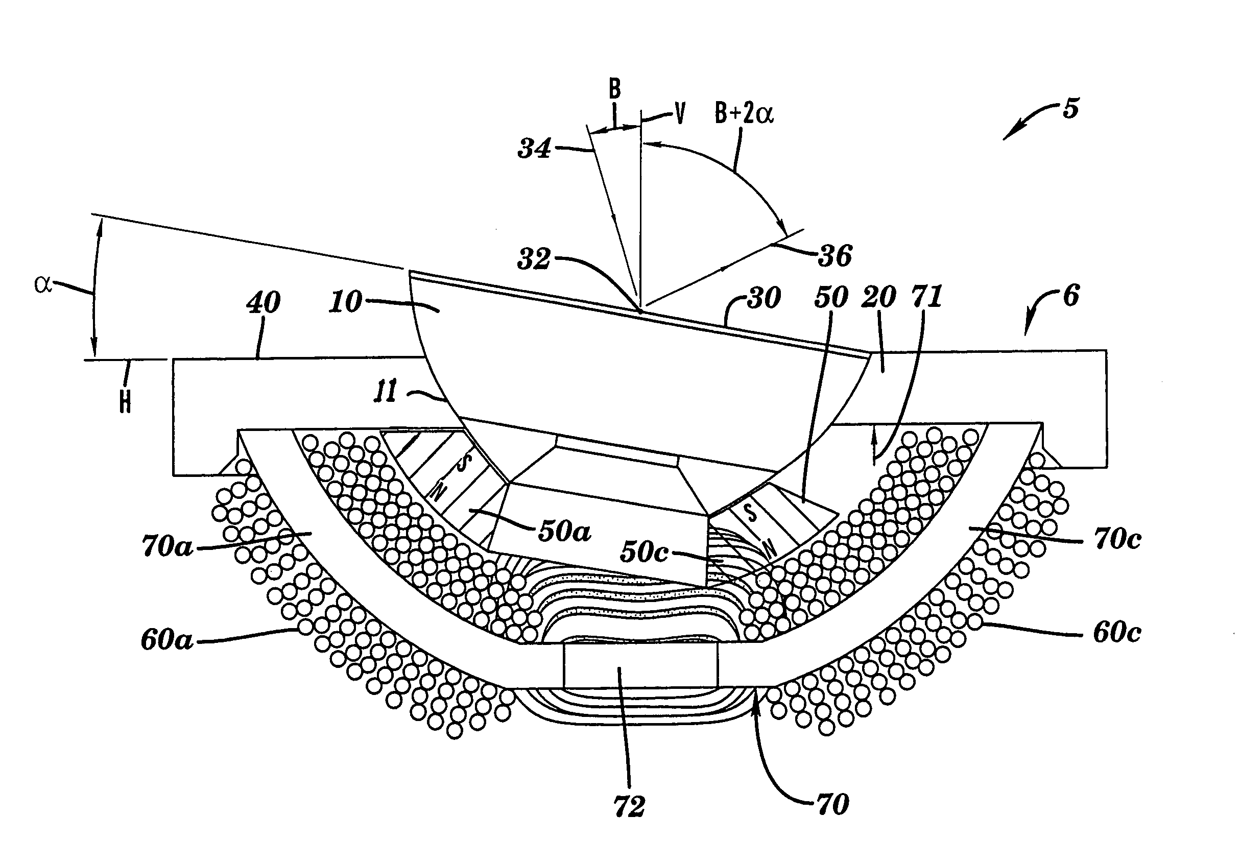
[0054]Referring now to FIGS. 3–7, there is illustrated the general layout of a preferred embodiment of the invention. FIG. 3A depicts a sectional view showing a two axis optical beam steering apparatus 5 in the general form of a ball and socket assembly. It is comprised of a movable member 10 in the form of a spherical or ball portion having an outer bearing surface 11 supported in a fixed member 40 that includes a spherical raceway or socket 20 for forming a seat in which the movable member 10...
PUM
 Abstract
Description
Claims
Application Information
PatSnap Eureka turns technology decisions into work you can execute. Powered by our Innovation Knowledge Graph, it runs expert workflows across engineering, life sciences, materials and intellectual property. Get your review-ready output in minutes.


