Image displaying method and image displaying device

a technology of image displaying and image, applied in the direction of picture reproducing devices, color signal processing circuits, instruments, etc., can solve the problems of degrading the color reproducibility of the entire system, difficult to secure compatibility with the srgb display, etc., and achieve the effect of extending the color gamut and broadening the color gamu

Active Publication Date: 2006-10-31
PANASONIC CORP
View PDF6 Cites 41 Cited by
  • Summary
  • Abstract
  • Description
  • Claims
  • Application Information

AI Technical Summary

Benefits of technology

[0012]An image display method of the present invention involves an image display method employing lights of four or more primary colors. The xy chromaticity and luminance ratio of primary color R, primary color G, and primary color B are the same as those of the sRGB display. Images are displayed by mixing these three primary color lights and a fourth primary color light. The fourth primary color light is in the visible region on the xy chromaticity diagram, possesses xy chromaticity outside the triangular region formed by primary color R, primary color G, and primary color B; and has luminance lower than that of primary color G. This makes it possible to maintain compatibility with the sRGB display, and also to broaden the color gamut.
[0025]As described above, the present invention offers an image display device which maintains compatibility with existing sRGB displays and has a broader color gamut three-dimensionally by employing four or more primary colors.

Problems solved by technology

For example, even though the camera captures accurate color information, the color reproducibility of the entire system is degraded if the display can only display color information inappropriately.
However, the above conventional image display device has the following disadvantages.
This makes it difficult to secure compatibility with the sRGB display when the fourth primary color is added.

Method used


Image

  • Image displaying method and image displaying device
  • Image displaying method and image displaying device
  • Image displaying method and image displaying device

Examples


first exemplary embodiment

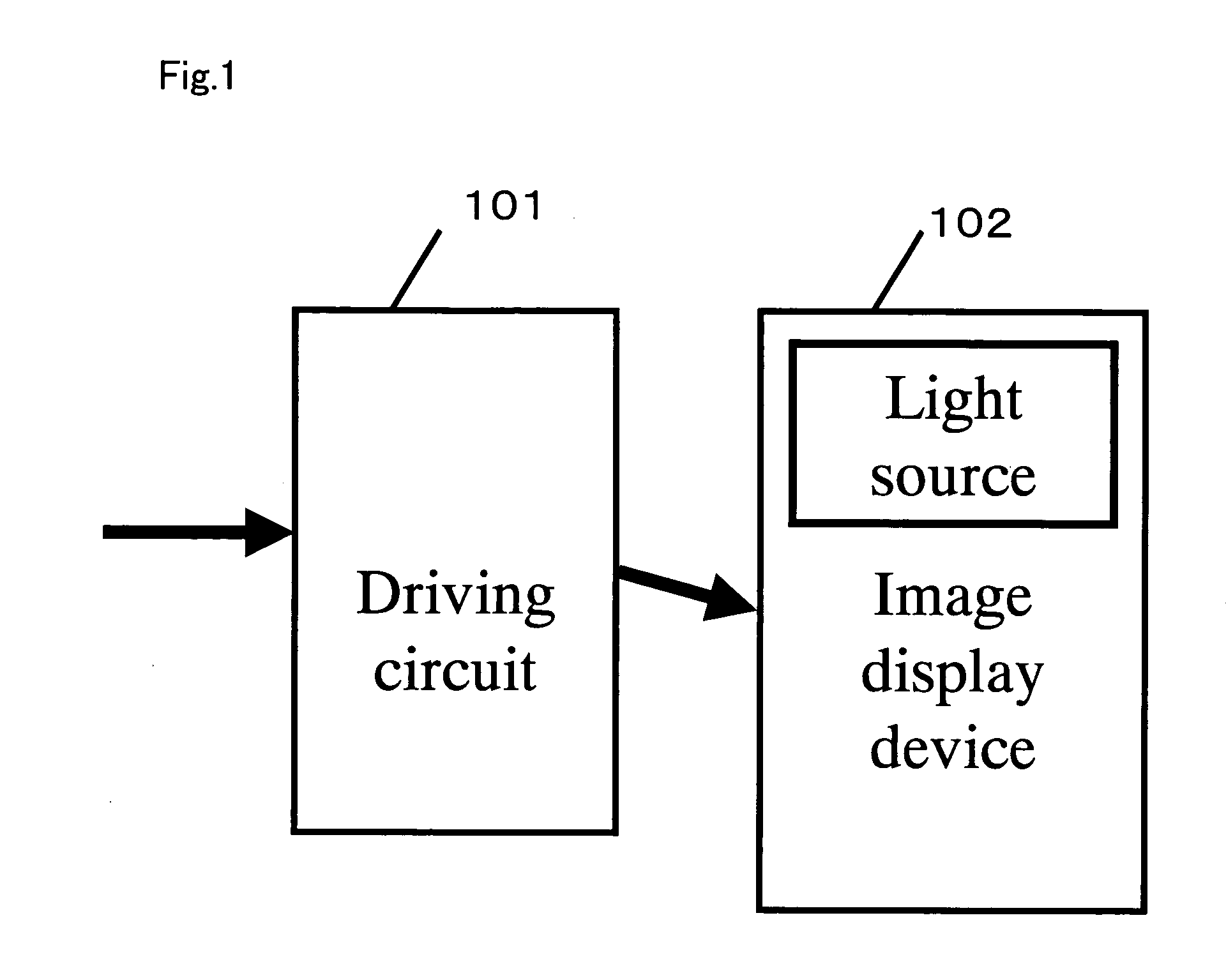
[0040]FIG. 1 shows a configuration of an image display system in a first exemplary embodiment of the present invention.

[0041]In FIG. 1, driving circuit 101 is a circuit for generating a modulation element driving signal for displaying images when a video input signal is input. Image display device 102 creates all the RGBC primary color lights from light source 103, and supplies them to spatial modulation elements respectively, and video lights modulated by the modulation element driving signal are synthesized and then output for display.

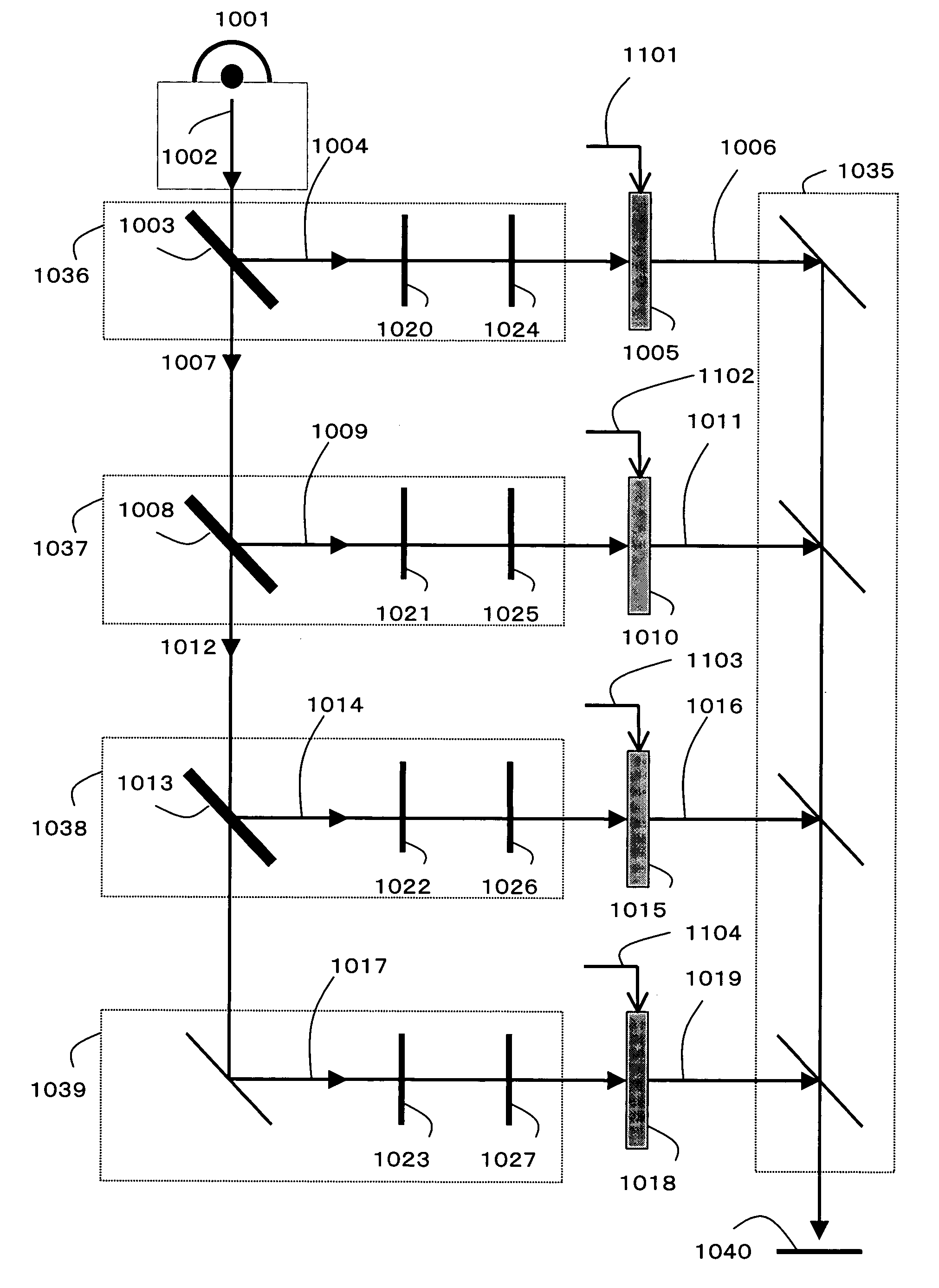
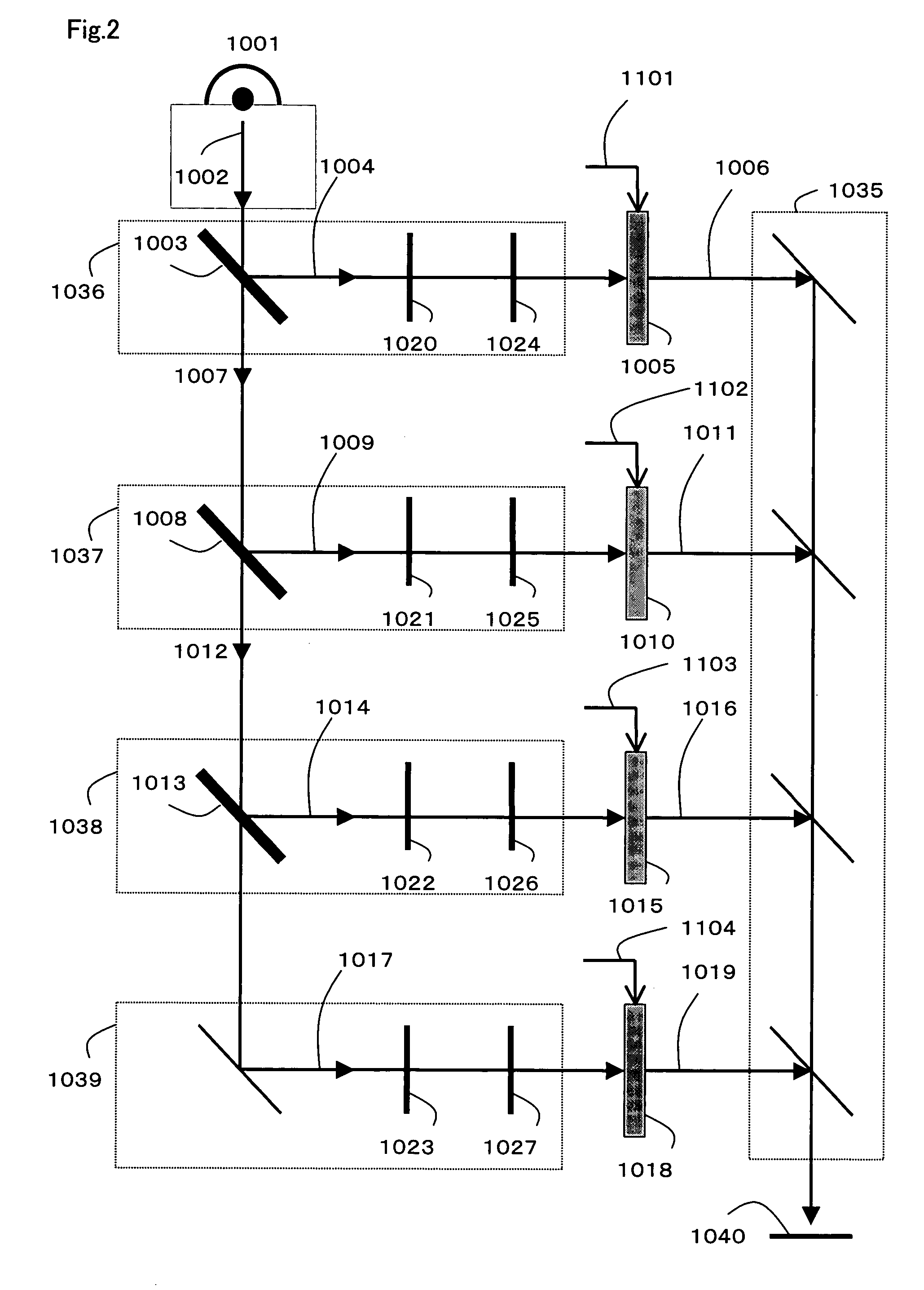
[0042]FIG. 2 is an example of the configuration of an image display device having four primary colors (hereafter referred to as a “4-primary color display”).

[0043]Light 1002 from light source 1001 enters first dichroic mirror 1003 in primary color B generating unit 1036, and the short wavelength components are reflected here so as to generate B-primary color light 1004. B-primary color light 1004 is generated in a way such that its xy chromaticity be...

second exemplary embodiment

[0113]FIG. 8 is the configuration of a 4-primary color liquid crystal display in a second exemplary embodiment of the present invention.

[0114]In FIG. 8, the light emitted from light source 8001 is reflected on reflector 8002, and enters liquid crystal panel 8003. Liquid crystal panel 8003 is demodulated by the operation of liquid crystal panel driving circuit 8005 driven by a video signal given by video memory 8004, and video tone is expressed as light intensity. The light passing through liquid crystal panel 8003 enters color filter panel 8006, and spectral energy distribution is changed and output based on the optical absorption characteristic of the colored material.

[0115]Color filter panel 8007, which is a fragmentary magnified view to show the structure of color filter panel 8006, consists of four color filters: B-filter 8008, G-filter 8009, R-filter 8010, and C-filter 8011. These four color filters are disposed in units of 2×2 cells. The video signal is sent to this 2×2 cell a...

third exemplary embodiment

[0120]FIG. 9 is the configuration of a liquid crystal display having five primary colors in a third exemplary embodiment of the present invention.

[0121]Color filter panel 9006 is different from the liquid crystal display of the second exemplary embodiment in FIG. 8.

[0122]Color filter 9007, which is a fragmentary magnified view of color filter panel 9006, consists of five color filters as one pixel: B-filter 9008, G-filter 9009, R-filter 9010, C1-filter 9011, and C2-filter 9012. As in the second exemplary embodiment, the spectral transmittance is designed such that lights passing B-filter 9008, G-filter 9009, and R-filter 9010 have chromaticity coordinates conforming to Rec. 709 for primary color B, primary color G, and primary color R. Primary color C1 and primary color C2 act in the same way as C-primary color 4004, and are arranged in regions given names such as blue, blue green, and green, contributing to broadening of the color gamut.

[0123]This configuration requires the develop...


PUM


Abstract

When displaying an image with at least four primary colors mixed, there are provided a primary color B generating unit (1036) having, as an xy chromaticity, (x, y)=(0.150, 0.060) and generating a primary color B lowest in luminance, a primary color G generating unit (1038) having, as an xy chromaticity, (x, y)=(0.300, 0.600) and generating a primary color G highest in luminance, and a primary color R generating unit (1037) having, as an xy chromaticity, (x, y)=(0.640, 0.330) and generating a primary color R higher in luminance than the primary color B and lower in luminance than the primary color G, whereby it is possible to expand a color gamut while ensuring compatibility with 3-primary-color image signal by allowing three primary colors to agree with the primary color Rec. 709 of a standard display sRGB.

Description

[0001]This application is a U.S. National Phase application of PCT International Application PCT / JP02 / 10991.TECHNICAL FIELD[0002]The present invention relates to image display methods for computer displays and image display devices receiving TV broadcasts using four or more primary colors, and image display devices using these methods.BACKGROUND ART[0003]Cross-media systems, in which a variety of image apparatuses are connected to an open system, are becoming very popular in response to advances in digital image apparatuses and network technology centering on the Internet. In open systems, image apparatuses and applications need to have a common interface and establish a configuration with high versatility and extendibility. From the aspect of color reproduction, an image apparatus sending color information, i.e., a camera or scanner, needs to send accurate color information captured to the open system. On the other hand, an image apparatus receiving and displaying color information...

Claims


Application Information

Patent Timeline
Patent Type & Authority Patents(United States)
IPC IPC(8): G09G5/02G06T1/00G02B27/14G09G3/20G09G3/36H04N9/12H04N9/30H04N9/31
CPCG02B27/1046G02B27/145G09G3/3413G09G5/02H04N9/30H04N9/3105H04N9/3197G09G3/20G09G3/3611G09G2300/0452H04N9/64
Inventor MOTOMURA, HIDETO
Owner PANASONIC CORP
Why Eureka
Try Eureka