Metrology system and method for measuring five degrees-of-freedom for a point target

a technology of point targets and metals, applied in the field of metalrology systems, can solve the problems of increasing the difficulty of maintaining the alignment of elements using rigid structural designs alone, the relative positioning between the reflector and feed components becomes increasingly difficult to maintain and/or control, and achieves the effect of facilitating the active compensation of large spacecraft systems and structures

Inactive Publication Date: 2006-10-31
THE BOEING CO
View PDF4 Cites 23 Cited by
  • Summary
  • Abstract
  • Description
  • Claims
  • Application Information

AI Technical Summary

Benefits of technology

[0009]The present invention provides a high precision metrology system that enables determination of the relative orientation of one point relative to another with 5 degrees-of-freedom. The present invention further provides a metrology system that is suitable for, but not limited to, facilitating active compensation of large spacecraft systems and structures. The present invention further provides a metrology system that may have a complimentary distant measurement system integrated to enable the measurement of a sixth degree-of-freedom. The present invention still further provides a method for remotely measuring 5 degrees-of-freedom for a point target.
[0016]There has, therefore, arisen a need to provide a high precision metrology system that facilitates active compensation of large spacecraft structures. There has further arisen a need to provide a metrology system that makes it possible to determine the relative location and orientation of key elements of spacecraft structures including antenna systems with very large fixed antenna reflectors. There has still further arisen a need to provide a metrology system that enables space missions where high antenna gains, high powers, and extremely tight pointing budgets are required. There has also arisen a need to provide a metrology system that is less complex than existing systems and that can be manufactured and integrated with spacecraft systems at a lower cost. There has still further arisen a need to provide a method for determining the relative orientation of one point relative to another that is not limited to 3 degrees-of-freedom.

Problems solved by technology

In the case of widely spaced but structurally connected alignment-critical elements, however, it becomes increasingly difficult to maintain the alignment of the elements using rigid structural designs alone.
While increasing the size of the reflector and the spacing from the feed can increase antenna performance from an electromagnetic point of view, the required precision and stability of the structure becomes harder to maintain.
For instance, the relative positioning between the reflector and feed components becomes increasingly difficult to maintain and / or control as the size of the space structure, and in particular the length of the boom and the size of the fixed antenna reflector, increases.
Additional concerns arise because the structure mass is limited by the launch vehicle's lift capacity.
Consequently, the mass density of the space structure is likely to drop and the dynamic stability of the resulting structure will decrease.
However, these systems have multiple implementation issues that limit their use.
For instance, currently existing metrology systems may be relatively expensive and heavy, requiring extensive cabling between the metrology system and the remote point to be measured, scanning mirrors and motors.
Furthermore, currently existing metrology systems may be complex to execute, for instance, requiring digital processing of the received data.
However, while these systems may be able to meet near-term needs, the measurement precision and accuracy of currently existing metrology systems may not scale as well as will be needed to control future large space structures.
The prior art system disclosed by Elliott et al. is relatively complex, including scanning mirrors that are rotated and therefore, may be prone to mechanical failure during operation in space.
Furthermore, the geometrical arrangement of determining angular position of targets does not scale well as the size of the structure increases and, in general, such a scheme will have geometrically decreased accuracy at longer distances.
However, Bennett and Batroney neither consider, disclose, nor suggest measurement of the other degrees of freedom, such as pitch and yaw rotations of the target.
Additionally, the method of Bennett and Bartroney may be unable to differentiate between lateral translations and rotations.

Method used


Image

  • Metrology system and method for measuring five degrees-of-freedom for a point target
  • Metrology system and method for measuring five degrees-of-freedom for a point target
  • Metrology system and method for measuring five degrees-of-freedom for a point target

Examples


Embodiment Construction

[0030]The following detailed description is of the best currently contemplated modes of carrying out the invention. The description is not to be taken in a limiting sense, but is made merely for the purpose of illustrating the general principles of the invention, since the scope of the invention is best defined by the appended claims.

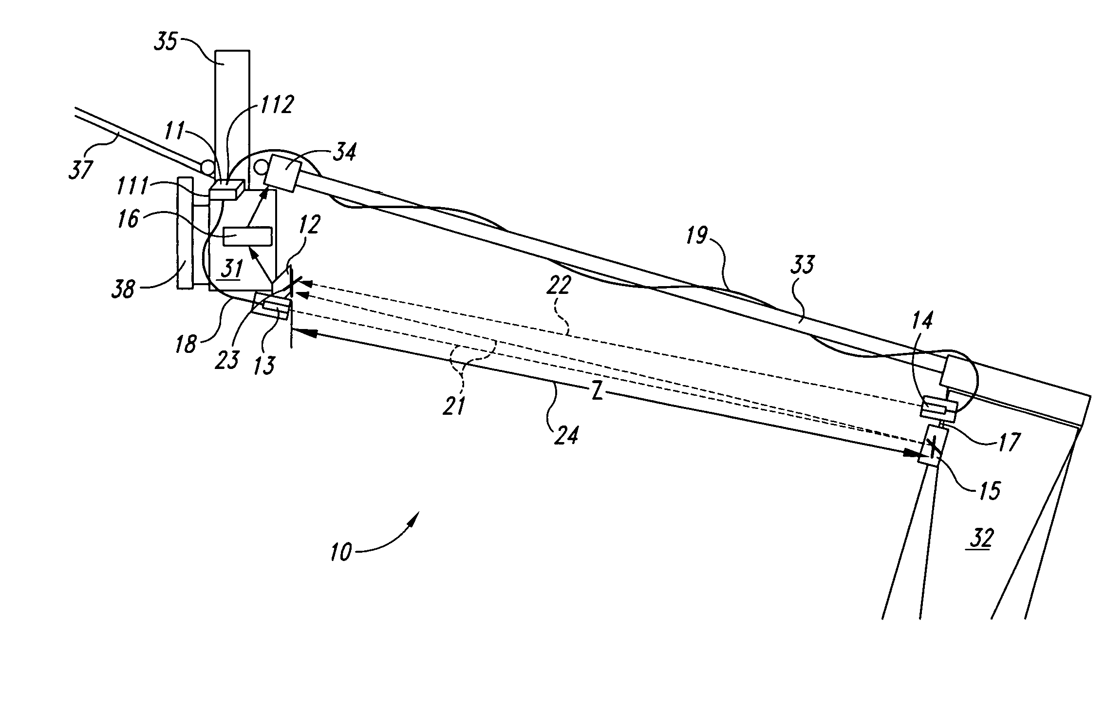
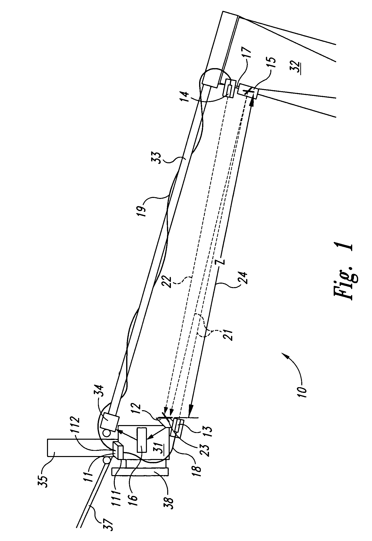
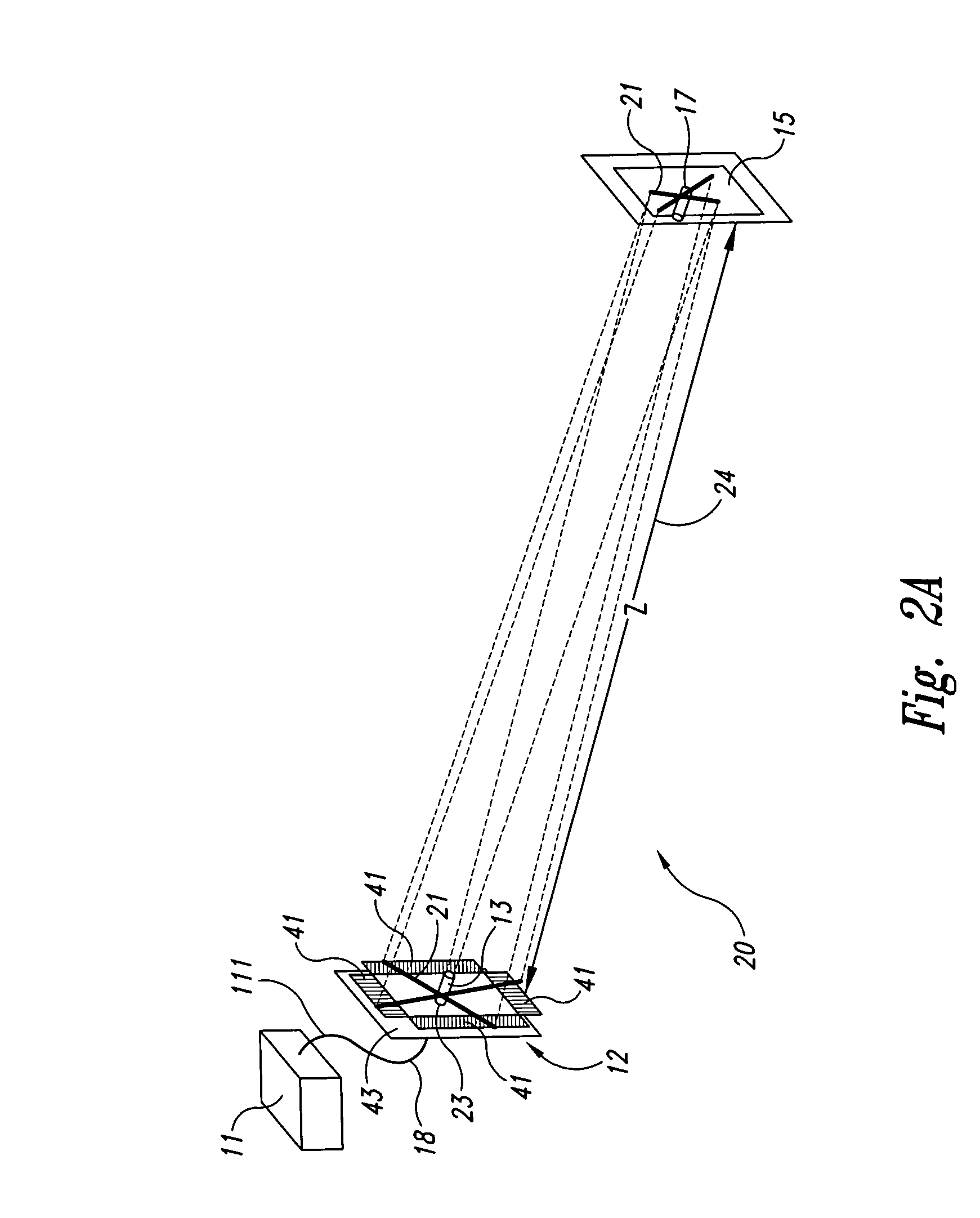
[0031]Broadly, an embodiment of the present invention provides a metrology system that enables determination of the relative orientation of one point relative to another with five degrees-of-freedom. Contrary to the known prior art, the metrology system as in one embodiment of the present invention includes a second collimator that generates a second laser crosshair enabling differentiation of pitch and yaw rotation from translation and roll rotation. The metrology system as in one embodiment of the present invention may be used, for example, for large spacecraft systems and structures having a large fixed reflector to determine the location and orienta...


PUM


Abstract

A metrology system includes a laser, a position sensitive detector array, a first collimator, a second collimator, and a mirror. The position sensitive detector array and the first collimator are positioned at a reference point. The second collimator and the mirror are positioned at a point target at a distance from the reference point. A laser beam is alternately provided to the first collimator and the second collimator by optical fiber. The position sensitive detector array measures position data from a first laser crosshair generated by the first collimator and from a second laser crosshair generated by the second collimator. By alternating the activation of the first collimator and the second collimator it is possible to measure 5 degrees-of-freedom for the point target. A metrology system processing unit provides analog data processing. The metrology system that is suitable for, but not limited to, facilitating active compensation of large spacecraft structures.

Description

BACKGROUND OF THE INVENTION[0001]The present invention generally relates to metrology systems and, more particularly, to a metrology system that enables determination of the relative orientation of one point relative to another with five degrees-of-freedom and to a method for remotely measuring five degrees-of-freedom for a point target.[0002]In an effort to enhance the performance and functionality of modern large space structures, such as satellites and other spacecraft, one class of structural designs increasingly features extended structures. Such structures may include large planar or boom-type structures that may have alignment-critical elements. In the case of widely spaced but structurally connected alignment-critical elements, however, it becomes increasingly difficult to maintain the alignment of the elements using rigid structural designs alone. Other means of compensating the deformation of the structure must be employed. However, in order to compensate for structural de...

Claims


Application Information

Patent Timeline
Patent Type & Authority Patents(United States)
IPC IPC(8): G01B11/26G01C1/00G01C15/00
CPCG01C15/002
Inventor BARVOSA-CARTER, BILLMASSEY, CAMERONDOTY, ROBERT EMMETTHERRERA, GUILLERMO
Owner THE BOEING CO
Why Eureka
Try Eureka