Switching power supply with a snubber circuit

a technology of switching power supply and snubber circuit, which is applied in the direction of power conversion systems, electric variable regulation, instruments, etc., can solve the problems of reducing the overall efficiency of the power supply, generating heat which has to be dissipated, and generating losses, so as to reduce the voltage drop, and reduce the effect of reverse recovery tim

Inactive Publication Date: 2006-10-31
DET INT HLDG LTD
View PDF11 Cites 21 Cited by
  • Summary
  • Abstract
  • Description
  • Claims
  • Application Information

AI Technical Summary

Benefits of technology

[0008]As this energy can be used to drive a load being connected to the power supply, it does not have to be dissipated. Therefore, lower currents and / or voltages within the power supply are necessary in order to reach the same power level as in a known power supply. This in turn enables the usage of electrical and / or magnetic components with a lower nominal power, which typically have lower losses, resulting in a power supply with a higher efficiency and a lower EMI (electromagnetic interference). Moreover, since the load on most of the components of the power supply is reduced, a smaller failure rate can be achieved.
[0010]One advantage of this snubber circuit is, that it limits the overvoltage across the output rectifier diodes, which for example are arranged as a full bridge rectifier connected to the secondary winding. That is why it is possible to make use of diodes for lower voltages. As low voltage diodes typically have a smaller voltage drop and a shorter reverse recovery time than high voltage diodes, their usage typically results in a higher efficiency and in a lower EMI.
[0011]The snubber circuit described is well suited for usage in a DC / DC converter. However, as every DC / DC power supply easily can be converted to an AC / DC power supply by adding an input rectifier-and connecting an AC power source, this snubber circuit can also be used with an AC / DC power supply.
[0014]By using two transformers in parallel on the primary side, the RMS (root mean square) current in the input capacitor of the power supply, which typically is an electrolytic capacitor, can be reduced. Furthermore, as a result of this design, the frequency on the secondary side of the power supply is multiplied by four. This enables to reduce the size of the output choke for high power applications, resulting in a smaller and lower-cost power supply.
[0028]In order to simplify the implementation of the power supply and to reduce the costs, the two output inductors can be realised by looping the windings of both inductors around the same magnetic core.

Problems solved by technology

Since a snubber circuit typically comprises resistors, capacitors, diodes and / or inductors, they generate losses and produce heat which has to be dissipated.
Generally spoken, they lower the overall efficiency of the power supply.

Method used


Image

  • Switching power supply with a snubber circuit
  • Switching power supply with a snubber circuit

Examples


Embodiment Construction

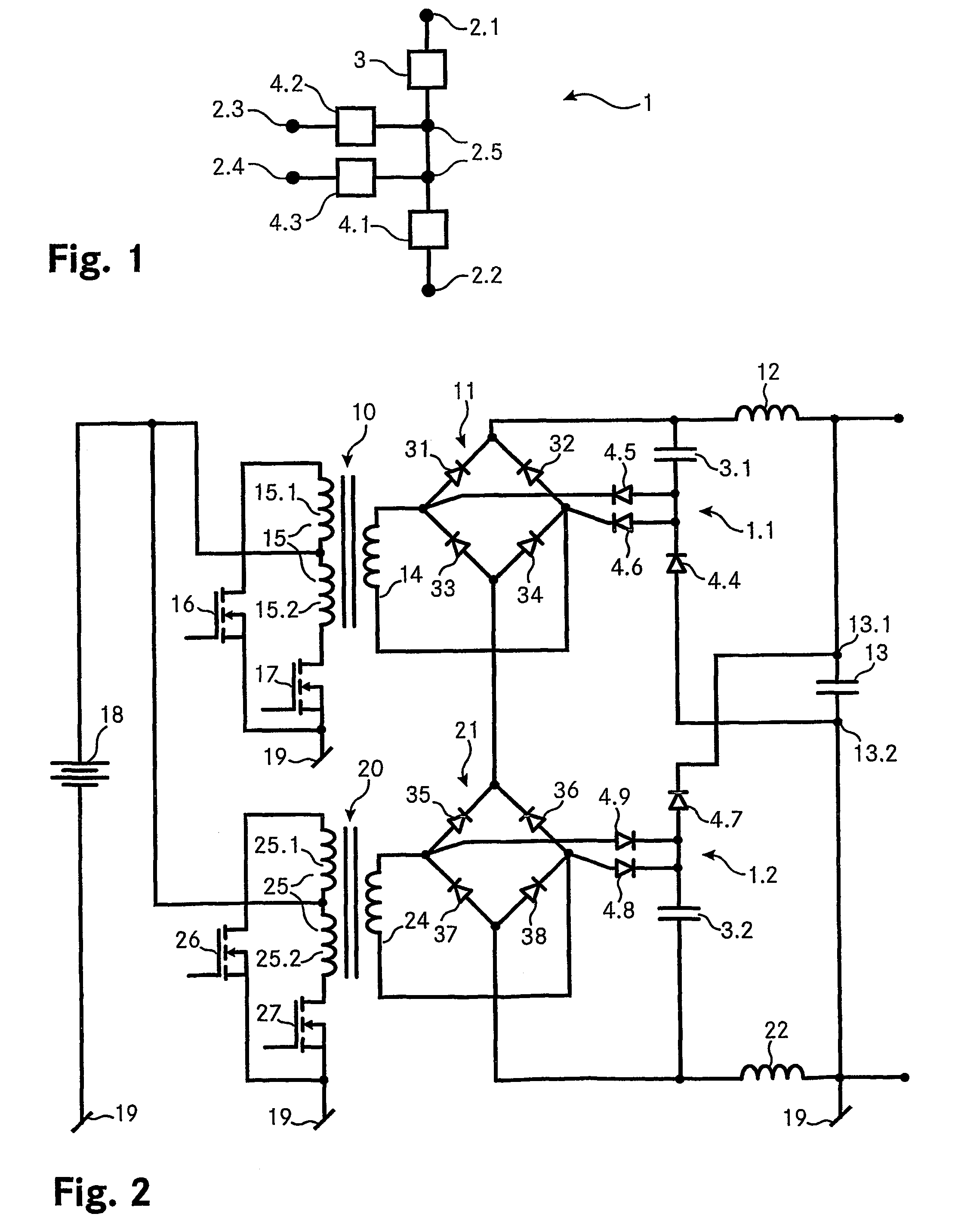
[0034]FIG. 1 shows a snubber circuit 1 according to the invention. The snubber circuit 1 comprises several terminals 2.1, 2.2, 2.3, 2.4, 2.5 which are used for connecting the snubber circuit 1 to a power supply and for connecting the components of the snubber circuit 1 itself. The snubber circuit comprises a capacitor 3 and three diodes 4.1, 4.2, 4.3 whereby capacitor 3 and diode 4.1 are connected in series via terminal 2.5. The other diodes 4.2, 4.3 are also connected to terminal 2.5 with one of their electrodes.

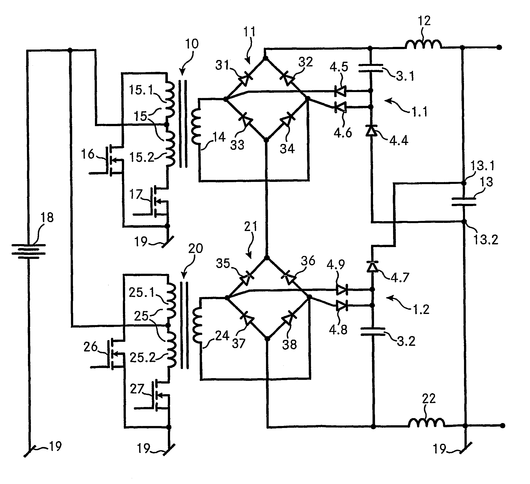
[0035]FIG. 2 shows a power supply according to the invention, which comprises two snubber circuits 1.1, 1.2 as shown in FIG. 1. The power supply converts a DC input voltage from a voltage source 18 to a DC output voltage which is provided across the terminals 13.1, 13.2 of an output capacitor 13. A load (not shown) can be connected across the output capacitor 13.

[0036]The DC / DC converter comprises two transformers 10 and 20, each having a primary winding 15, 25 and a second...


PUM


Abstract

A DC / DC power supply with two transformers (10, 20), which for example are connected in parallel on the primary and in series on the secondary side, comprises two passive, non-dissipative snubber circuits (1.1, 1.2). Each snubber circuit comprises a series circuit formed by a capacitor (3.1, 3.2) and a diode (4.4, 4.7), which is connected to the output capacitor (13) of the power supply. The transformers are interleaved with a push-pull configuration. On the secondary side, the power supply has an output choke (12, 22) and two output rectifiers (11, 21) are connected to the secondary winding (14, 24) of each transformer. Each snubber circuit further comprises two additional diodes (4.5, 4.6, 4.8, 4.9), one electrode of these diodes being connected to the joint electrode of the snubber capacitor (3.1, 3.2) and the first snubber diode (4.4, 4.7) and the other electrodes being connected respectively to an end of the secondary winding (14, 24) of a transformer.

Description

TECHNICAL FIELD[0001]The invention relates to a switching power supply providing a DC output, the power supply having an output capacitor, a transformer with a primary and a secondary winding and a snubber circuit comprising a snubber capacitor and a first snubber diode. The invention further relates to a snubber circuit for such a switching power supply.PRIOR ART[0002]The number of electrically powered devices has increased enormously over the last decades. Accordingly, the demand for power supplies along with the requirements which they have to meet, has also increased. A low failure rate and high efficiency are among the most important requirements for power supplies.[0003]A widely used type of power supplies are the switching power supplies which typically are smaller, lighter and generate less heat than an equivalent linear power supply. To lower switching losses, to reduce the rate of current or voltage rise or to limit overvoltages so called snubber circuits were introduced.[...

Claims


Application Information

Patent Timeline
Patent Type & Authority Patents(United States)
IPC IPC(8): H02M3/337
CPCH02M3/337
Inventor MBAYE, FALL
Owner DET INT HLDG LTD
Why Eureka
Try Eureka