
Electrode configuration for resistivity sounding

a resistivity and sounding technology, applied in the field of resistivity surveys, can solve the problems of less successful applications on water, less suitable applications involving inversion of apparent resistivity data into true resistivity depth sections, and the electrical gradient cannot be considered linear, so as to reduce the noise level

Active Publication Date: 2006-11-07
DEMCO
View PDF8 Cites 25 Cited by
  • Summary
  • Abstract
  • Description
  • Claims
  • Application Information

AI Technical Summary

Benefits of technology

This configuration improves the accuracy of resistivity measurements by maintaining low geometrical factors, increasing signal / noise ratios, and enabling effective noise correction, resulting in higher vertical resolution and more accurate inversion of resistivity data for water-covered subsurfaces.

Problems solved by technology

Although the method is generally well accepted for land applications it tends to be less successful in applications on water requiring for instance accurate determination of depths and thicknesses of sea and river sediments and other geological structures.
The dipole-dipole configuration is known to be very sensitive to lateral subsurface variations and is therefore less appropriate for applications involving inversion of apparent resistivity data into true resistivity depth sections.
If this ratio is chosen too large the electrical gradient can not be considered linear.
A very low ratio on the other hand results in very high geometrical factors and thus very poor signal / noise ratios.
As a high signal / noise ratio is essential for apparent resistivity data to be successfully inverted into true resistivity depth sections, the “Asymmetric Inverse Schlumberger” configuration, which may be appropriate in qualitative applications involving simple apparent resistivities and / or formation factors, is generally less successful in quantitative resistivity applications involving inversion into sediment depths and thicknesses.

Method used


Image

  • Electrode configuration for resistivity sounding
  • Electrode configuration for resistivity sounding

Examples


Embodiment Construction

[0022]The invention relates to a method for measuring high quality apparent resistivities of water covered subsurfaces which can be used for inversion into true vertical depth sections.

[0023]Resistivity of the upper soils of a water bed is determined by measuring a voltage gradient associated with an electrical field of an electrical current that is injected into the subsurface.

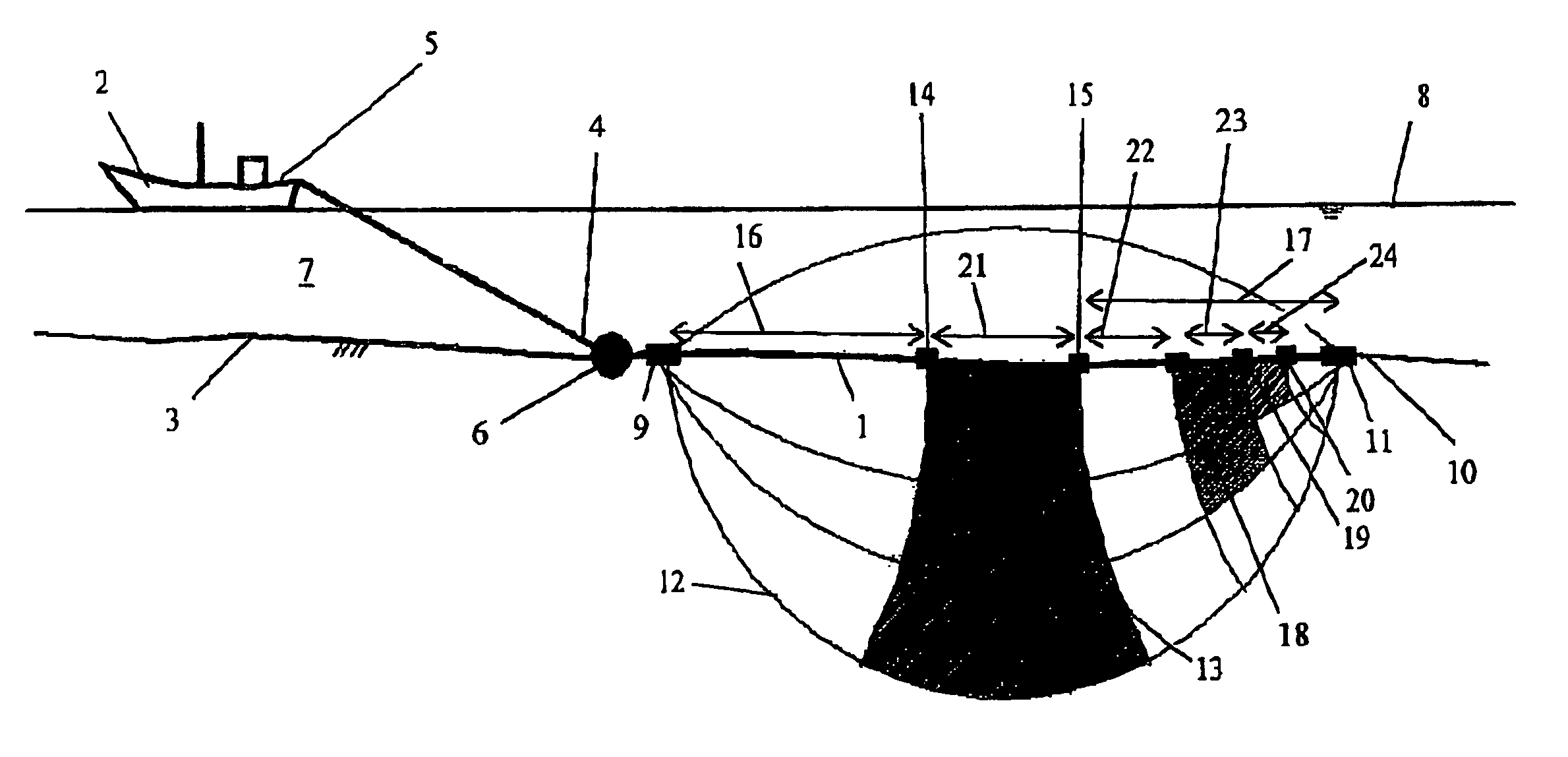
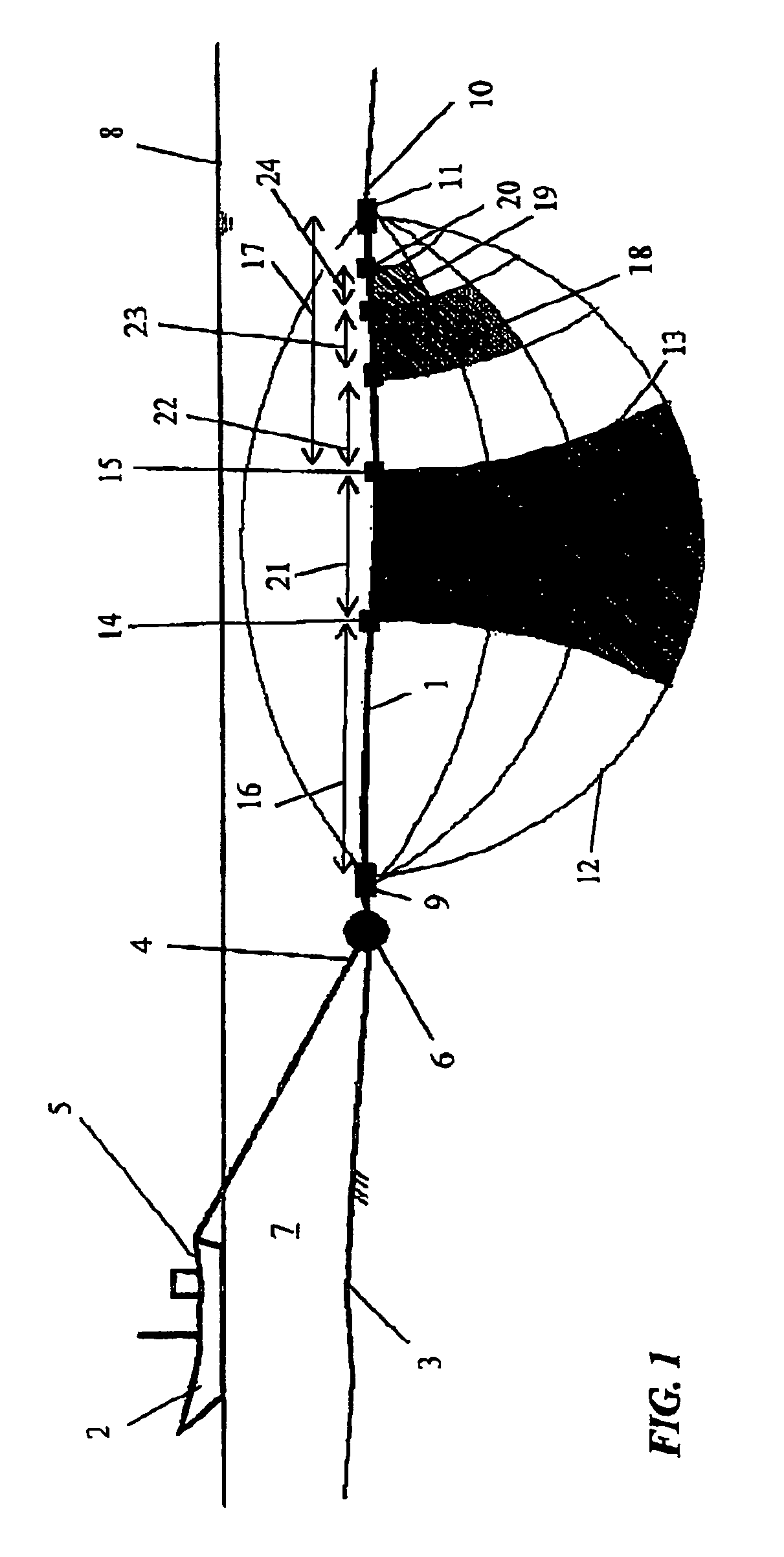
[0024]To this end, a substantially flexible multi-channel cable 1 with an array of electrodes, according to an embodiment of the invention, is towed by a survey vessel 2 along the water covered subsurface 3 as represented schematically in FIG. 1. This water covered subsurface or water bed 3 can be for instance a sea bed or river bed.

[0025]The electrodes are arranged separated from each other in the following fixed order from a first end 4 towards a second end 10 of the cable 1: (i) a first current electrode 9, (ii) a first voltage electrode 14, (iii) a second voltage electrode 15, (iv) a third voltage electro...


PUM


Abstract

Device for resistivity soundings on water covered subsurfaces including a Fixed Current Asymmetric Schlumberger electrode configuration with a first and second current electrode and a number of voltage electrodes that are positioned on one line between the current electrodes, and method for measuring the apparent resistivity of water covered subsurfaces using said device and electrode configuration whereby a voltage gradient associated with a generated electrical field between the current electrodes, is measured between the voltage electrodes such that it allows noise recognition and noise filtering by Coupled Electrode Noise Filtering.

Description

FIELD OF THE INVENTION[0001]The present invention relates to a method for resistivity surveys on water, i.e. for measuring of apparent resistivity of water covered subsurfaces using a multi-channel cable carrying an electrode array. In particular the present invention relate, to a new electrode configuration and a method for noise recognition and noise filtering as used in quantitative resistivity applications involving inversion of resistivity data into true depth sections.BACKGROUND OF THE INVENTION[0002]Resistivity sounding is a well known geophysical method used in geological applications on land as well as on water. Although the method is generally well accepted for land applications it tends to be less successful in applications on water requiring for instance accurate determination of depths and thicknesses of sea and river sediments and other geological structures.[0003]Many existing electrode configurations have been derived from the “Normal Schlumberger” electrode configur...

Claims


Application Information

Patent Timeline
Patent Type & Authority Patents(United States)
IPC IPC(8): G01V3/02G01R27/08G01V3/04
CPCG01V3/02Y02A90/30
Inventor BRABERS, PETERALV
Owner DEMCO
Learn More