Linearizing apparatus and method

a linearizing apparatus and linearization technology, applied in the direction of electric variable regulation, process and machine control, instruments, etc., can solve the problems of inability to accurately store coefficients, comparatively difficult to achieve, and high nonlinear tuning or frequency response of plate topology as a function,

Inactive Publication Date: 2006-11-07
RGT UNIV OF MICHIGAN
View PDF21 Cites 12 Cited by
  • Summary
  • Abstract
  • Description
  • Claims
  • Application Information

AI Technical Summary

Benefits of technology

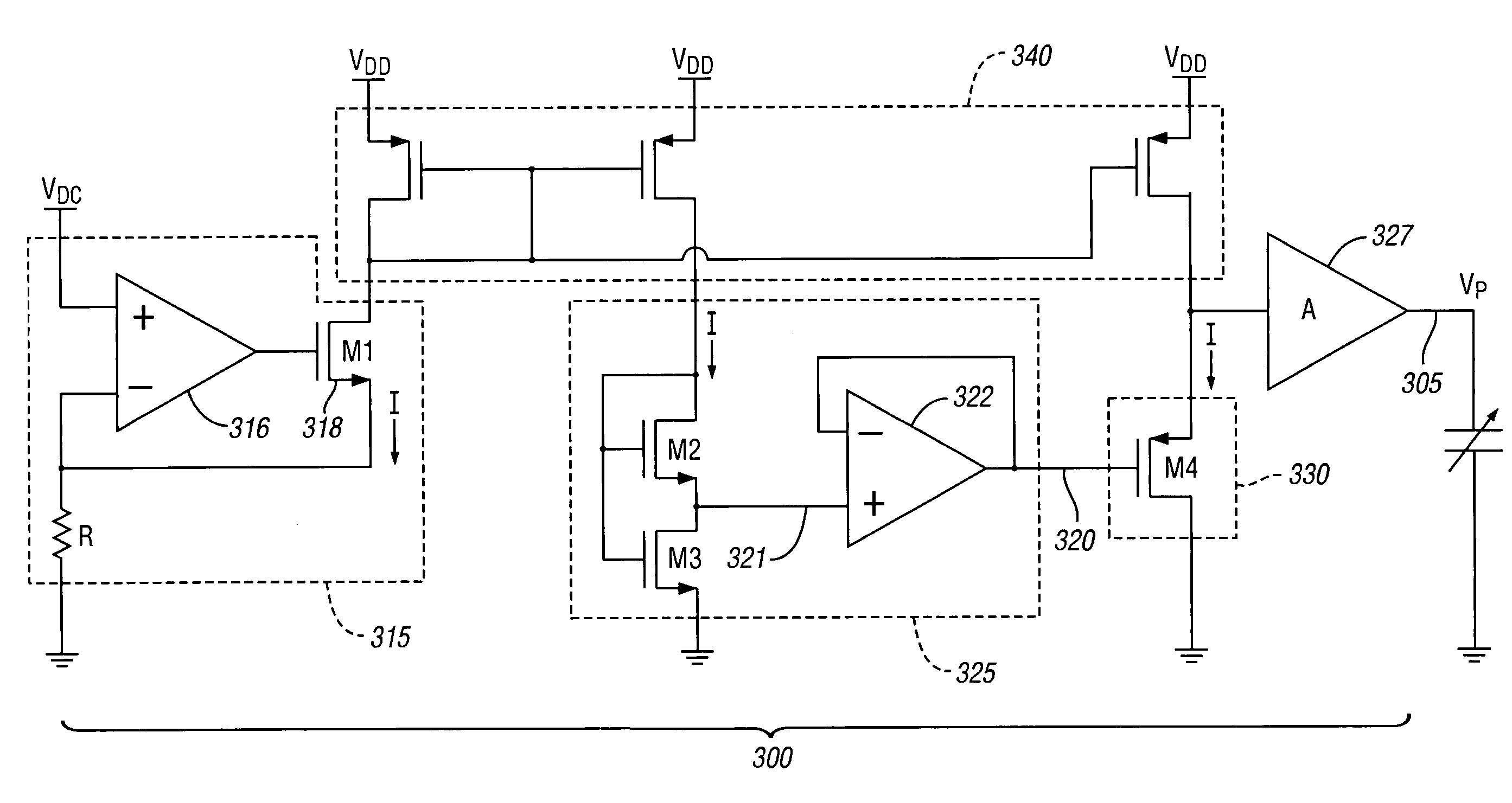
[0020]An apparatus embodiment of the present invention provides a substantially linear relationship between an input signal, such as an input voltage, and a selected parameter, such as a frequency response of an oscillator or capacitor. The various embodiments generate an applied signal which is effectively pre-distorted, such that when it is applied to such an oscillator or capacitor, it allows the selected parameter to vary substantially linearly with the input signal to, for example, tune an oscillator to a selected frequency.

Problems solved by technology

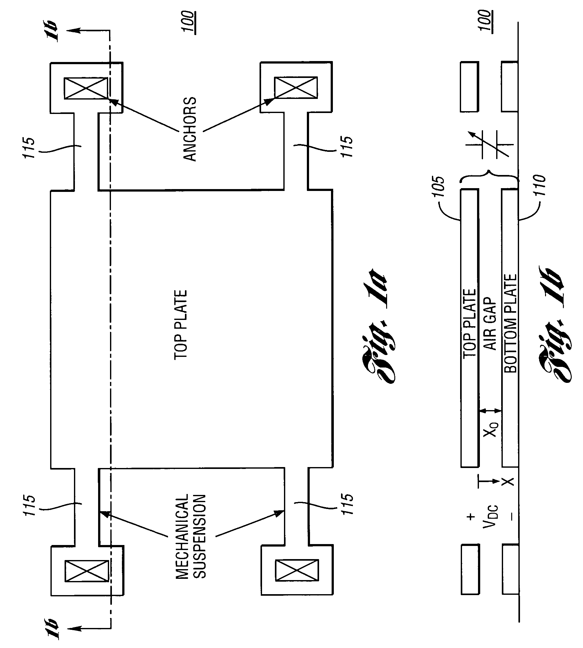
However, a significant drawback associated with the parallel plate topology is the highly nonlinear tuning or frequency response as a function of the electrostatic actuation of the device.
Tuning of such capacitors to a selected or predetermined frequency, as part of an oscillator, for example, as a nonlinear response, is comparatively difficult.
Such an implementation, however, requires additional processing circuitry, a memory circuit, and memory interface circuitry.
In addition, to the extent fabrication varies from assumed modeling parameters, such stored coefficients are inaccurate, and do not provide the desired result of tuning such a device to a selected frequency.

Method used


Image

  • Linearizing apparatus and method
  • Linearizing apparatus and method
  • Linearizing apparatus and method

Examples


first embodiment

Hence, if the input tuning voltage is preprocessed (to form an applied voltage) by applying a square root function (i.e., Vp=VDC1 / 2), the relationship between the input tuning voltage and x would be then be nearly linear for small x. This first embodiment in accordance with the present invention resulted in a correlation coefficient (R2) of 0.9870 between the achieved response and the least squares linear fit to the function (these results are illustrated in FIG. 4 as the “square root preprocessor” curve).

second embodiment

[0062]More accurate linearization was achieved in accordance with the present invention by expanding Equation 11 to show the relationship between VDC and x is (Equation 14):

[0063]VD⁢⁢C=2⁢kmɛ⁢⁢A⁢(x⁢xo-x32)=a⁢x-bx32

where a and b are constants. Although a square-root function is capable of being implemented with CMOS electronics, it is quite difficult to realize a 3 / 2 power function. In accordance with the present invention, it was determined empirically that Equation 14 can be well approximated, utilizing a logarithmic function instead of the 3 / 2 power function, by the following (Equation 15):

[0064]a⁢x-b⁢⁢x32≈c⁢x+d⁢⁢ln⁡(xe)

where x is greater than 1 and a, b, c, d, and e are constants selected such that the fit is accurate. The preprocessed, applied voltage is then of the form (Equation 16):

[0065]VP=c⁢VD⁢⁢C+d⁢⁢ln(VD⁢⁢Ce)

where c, d, and e were chosen to provide an accurate fit. In accordance with the present invention, the natural logarithm as an approximation to the 3 / 2 power function ...

embodiment 500

[0089]FIG. 9 is a flow chart illustrating an exemplary linearizing method embodiment 500 in accordance with the present invention. As indicated above, this methodology may be performed by a processor 410, by the apparatuses 200 or 300, or by any other similarly or equivalently configured circuitry. The method may also be characterized as a method of pre-distorting a control signal to create an applied signal having a nonlinear relationship with a parameter (such as a circuit parameter) such that the control signal has a linear relationship with the parameter.

[0090]The method begins, start step 505, with reception of an input signal, such as an input voltage or input current. As mentioned above, depending upon the selected embodiment, conversion of the input signal may be necessary of desirable, such as conversion of an input voltage to an input current, or conversion of an analog input signal to a digital form, step 510. When such conversion is appropriate in step 510, the method pr...


PUM


Abstract

An apparatus and method are disclosed which provide a substantially linear relationship between an input signal, such as an input voltage or current, and a predetermined parameter, such as a frequency response or capacitance of a parallel plate capacitor or varactor. The apparatus comprises a square root converter and a logarithmic generator. The square root converter is adapted to provide a square root signal which is substantially proportional to a square root of the input signal. In the various embodiments, the logarithmic generator is adapted to provide an applied signal which is substantially proportional to a sum of a logarithm of the input signal plus the square root of the input signal. The applied signal is a pre-distorted signal which generally has a non-linear relation to the predetermined parameter and which, when applied, allows the predetermined parameter to vary substantially linearly with the input signal.

Description

CROSS-REFERENCE TO RELATED APPLICATIONS[0001]This application is related to Michael S. McCorquodale et al., U.S. Provisional Patent Application Ser. No. 60 / 464,760, entitled “A CMOS Voltage-to-Frequency Linearizing Circuit for Parallel Plate RF MEMS Varactors,” filed Apr. 23, 2003, incorporated by reference herein, with priority claimed for all commonly disclosed subject matter (the “first related application”).[0002]This application is related to Michael S. McCorquodale, U.S. Provisional Patent Application Ser. No. 60 / 555,193, entitled “Monolithic and Top Down Clock Synthesis with Micromachined Radio Frequency Reference,” filed Mar. 22, 2004, incorporated by reference herein, with priority claimed for all commonly disclosed subject matter (the “second related application”).BACKGROUND OF THE INVENTION[0003]1. Field of the Invention[0004]The present invention is related generally to linearizing apparatuses and methods, and more specifically, to apparatuses and methods which provide a...

Claims


Application Information

Patent Timeline
Patent Type & Authority Patents(United States)
IPC IPC(8): G06F7/556G06G7/122G06G7/24H03F3/16H03G1/00
CPCG06G7/122
Inventor MCCORQUODALE, MICHAEL S.BROWN, RICHARD B.DING, MEI KIM
Owner RGT UNIV OF MICHIGAN
Why Eureka
Try Eureka