Combined equalization for DMT-based modem receiver

a modem receiver and equalization technology, applied in the field of multi-carrier modulation communication, can solve the problems of loss of orthogonality among the receivers, the non-ideal impulse response of the transmission channel, and the poor snr of some subchannels

Active Publication Date: 2006-11-07
TEXAS INSTR INC
View PDF1 Cites 4 Cited by
  • Summary
  • Abstract
  • Description
  • Claims
  • Application Information

AI Technical Summary

Benefits of technology

[0032]It is therefore an object of this invention to provide a method and receiver modem system for implementing an efficient per-tone equalization scheme for DMT communications.

Problems solved by technology

Indeed, the SNR of some subchannels is so poor that these subchannels are unloaded, carrying no bits.
However, the non-ideal impulse response of the transmission channel distorts the transmitted signal.
ICI affects the independence of the subcarriers, resulting in loss of orthogonality among the subchannels, which in turn prevents separation of the modulating data on these subchannels at the receiver.
This presents a tradeoff between interference and data rate in conventional DMT communications.
As a result, conventional TEQ optimization is not suited for optimizing the signal-to-noise performance of the subchannels.
As such, conventional TEQ training does not result in optimum bitloading capacity for the DSL communications session.
However, it has also been observed, in connection with this invention, that the per-tone equalization approach described by Van Acker et al. is subject to several significant limitations when realizing this approach in actual DMT modems for DSL communications.
The computational complexity for computing the ν−1 sliding FFTs, especially during a DSL session in which the equalizer taps ought to be updated to account for channel variation, is also a limitation on this approach.
As a result, per-tone equalization according to known technology is not available for DSL receiver modem architectures under current standards.

Method used


Image

  • Combined equalization for DMT-based modem receiver
  • Combined equalization for DMT-based modem receiver
  • Combined equalization for DMT-based modem receiver

Examples


Embodiment Construction

[0048]The present invention will be described in connection with an example of its implementation in a transceiver, such as a Digital Subscriber Line (DSL) modem. It will be apparent to those skilled in the art having reference to this specification that this invention is particularly well-suited for use in such an application. However, it is also contemplated that this invention will be of similar benefit in many other applications that involve discrete multitone modulation (DMT), including both land line and wireless communications. It is therefore to be understood that these and other alternatives to the embodiment described below are contemplated to be within the scope of the invention as claimed.

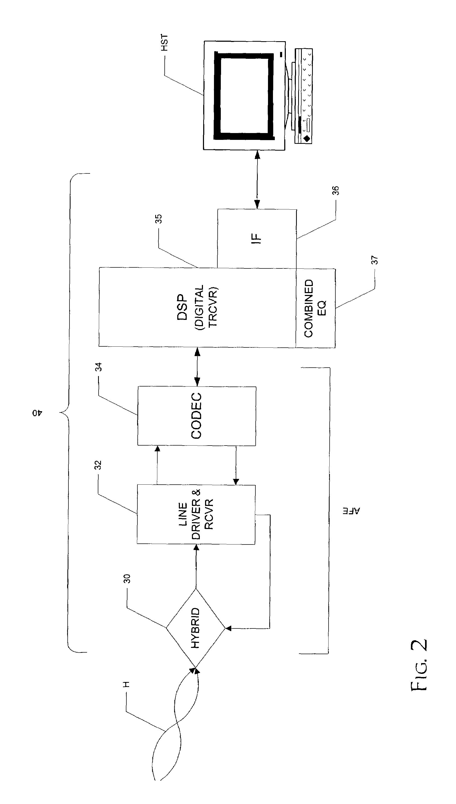
[0049]In this regard, and referring now to FIG. 2, an example of the construction of receiving modem 40 according to the preferred embodiments of the invention will now be described. Modem 40 in this example is in the form of a transceiver (i.e., for both transmitting and receiving) for...


PUM


Abstract

A DMT modem (40) is disclosed, in which a combined time domain equalizer and per-tone equalizer is applied to a received DMT signal. The combined equalizer includes a first FFT function (44) that is applied to a set of samples in a time-domain signal after the application of a time domain equalizer (42). The first FFT function (44) produces an initial FFT result, that is accumulated with a sliding FFT (46) performed upon difference values in the time domain samples. The sliding FFT results are applied to a per-ton equalizer (48) which applies a set of complex coefficients determined in training of the modem. A simple 1-tap FEQ (50) then can recover the signal. The combined equalizer enables per-tone equalization, in a manner that is compatible with conventional DSL training standards. According to a second embodiment, the per-tone equalization is performed only on selected tones of the multitone signal.

Description

CROSS-REFERENCE TO RELATED APPLICATIONS[0001]Not applicable.STATEMENT REGARDING FEDERALLY SPONSORED RESEARCH OR DEVELOPMENT[0002]Not applicable.BACKGROUND OF THE INVENTION[0003]This invention is in the field of communications, and is more specifically directed to multicarrier modulation communications, such as Digital Subscriber Line (DSL) communications.[0004]An important and now popular modulation standard for DSL communication is Discrete Multitone (DMT). According to DMT technology, the available spectrum is subdivided into many subchannels (e.g., 256 subchannels of 4.3125 kHz). Each subchannel is centered about a carrier frequency that is phase and amplitude modulated, typically by Quadrature Amplitude Modulation (QAM), in which each symbol value is represented by a point in the complex plane. The number of available symbol values for each subchannel, and thus the number of bits in each symbol communicated over that subchannel, is determined during initialization of the DMT com...

Claims


Application Information

Patent Timeline
Patent Type & Authority Patents(United States)
IPC IPC(8): H04B7/00H03K7/00H04B1/38H04L27/28H04L25/03
CPCH04L25/03159H04L2025/03484H04L2025/03414
Inventor LI, XIAOHUICURRY, MARK A.
Owner TEXAS INSTR INC
Why Eureka
Try Eureka